Download
1 / 20
280 likes | 1.54k Vues
Synthesis of one-port networks with two kinds of elements. 11.1 Properties of L-C immittance functions 11.2 Synthesis of L-C driving-point immittances. Contents. Properties of L-C immittance functions Properties Examples of immittance and non-immittance functions

E N D
Synthesis of one-port networkswith two kinds of elements 11.1Properties of L-C immittance functions 11.2 Synthesis of L-C driving-point immittances
Contents • Properties of L-C immittance functions • Properties • Examples of immittance and non-immittance functions • Synthesis of L-C driving-point immittance • Synthesis of L-C circuit • Examples of synthesis
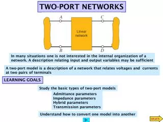
Property 1. L-C immittance function • 1. ZLC (s) or YLC (s) is the ratio of odd to even or even to odd polynomials. • Consider the impedance Z(s) of passive one-port network. (M is even N is odd) As we know, when the input current is I, the average power dissipated by one-port network is zero: Average Power= =0 (for pure reactive network)
OR Z(s) or Y(s) is the ratio of even to odd or odd to even!!
Property 2. L-C immittance function • 2.The poles and zeros are simple and lie on the axis. • Since both M and N are Hurwitz, they have only imaginary roots, and it follows that the poles and zeros of Z(s) or Y(s) are on the imaginary axis. • Consider the example
In order for the impedance to be positive real the coefficients must be real and positive. Impedance function cannot have multiple poles or zeros on the axis. The highest powers of the numerator and the denominator polynomials can differ by, at most, unity. Ex) highest order of the numerator : 2n -> highest order of the denominator can either be 2n-1 (simple pole at s= ) or the order can be 2n+1 (simple zero at s= ).
+2 +4 0 +1 +3 Property 3. L-C immittance function • 3.The poles and zeros interlace on the axis. X(w) Highest power: 2n -> next highest power must be 2n-2 They cannot be missing term. Unless? if s=0,
We can write a general L-C impedance or admittance as Since these poles are all on the jw axis, the residues must be real and positive in order for Z(s) to be positive real . S=jw Z(jw)=jX(w) (no real part)
Since all the residues Ki are positive, it is eay to see that for an L-C function Ex) X(w) w3 w2 w w4 0
Properties 4 and 5. L-C immittance function • The highest powers of the numerator and denominator must differ by unity; the lowest powers also differ by unity. • There must be either a zero or a pole at the origin and infinity.
Summary of properties 1. or YLC (s) is the ratio of odd to even or even to odd polynomials. 2. The poles and zeros are simple and lie on the jw axis 3. The poles and zeros interlace on the jw axis. 4. The highest powers of the numerator and denominator must differ by unity; the lowest powers also differ by unity. 5. There must be either a zero or a pole at the origin and infinity.
11.2 Synthesis of L-C Driving point immittances • L-C immittance is a positive real function with poles and zeros on the jw axis only. • The synthesis is accomplished directly from the partial fraction . • F(s) is impedance -> then the term : capacitor of 1/K farads the K(infinite)s is an inductance of K(infinite) henrys.
2h 2/9 f 15/8 h For Z(s) partial fraction Is a parallel tank capacitance and inductance. , 2/15f
2h 2/3 h 1f Y(S) 1/6 f 3/2 f For Y(s) partial fraction • In admittance
Another methodology • Using property 4 “The highest powers if numerator and denominator must differ by unity; the lowest powers also differ by unity.” • Therefore, there is always a zero or a pole at s=infinite . • suppose Z(s) numerator:2n ,denominator:2n-1 • this network has pole at infinite. -> we can remove this pole by removing an impedance L 1 s Z2 (s) = Z(s) - L 1 s • Degree of denominator : 2n-1 numerator:2n-2 • Z2 (s) has zero at s=infinite. • Y2 (s) =1/ Z2 (s) , Y3 (s) = Y2 (s) - C2 s
This infinite term removing process continue until the remainder is zero. • Each time we remove the pole, we remove an inductor or capacitor depending upon whether the function is an impedance or an admittance. • Final synthesized is a ladder whose series arms are inductors and shunt arms are capacitors.
2/3 h 1/4 f 3/4 f 2h 8/3 h 2h
This circuit (Ladder) called as Cauer because Cauer discovered the continues fraction method. • Without going into the proof of the statement m in can be said that both the Foster and Cauer form gice the minimum number of elements for a specified L-C network.
2/3 f 2/25 f 5/4 h 5 h Example of Cauer Method