Download
1 / 58
910 likes | 1.49k Vues
Electrical Circuits. What you need to Know!. Safety 2- Types of Current 3-Types of Electrical Circuits 2- Theories of Electron Flow OHMS Law Voltage Amperage Resistance Voltage Drop. Personal Safety practices. Remove jewelry, watches and rings Tie hair back and avoid loose clothing

E N D
What you need to Know! • Safety • 2- Types of Current • 3-Types of Electrical Circuits • 2- Theories of Electron Flow • OHMS Law • Voltage • Amperage • Resistance • Voltage Drop
Personal Safety practices • Remove jewelry, watches and rings • Tie hair back and avoid loose clothing • Be aware of other workers unsafe habits
SOURCES OF ELECTRICITY Electricity can be created by several means: Friction, Heat, Light, Pressure, Chemical Action, or Magnetic Action. Only a few of these sources of energy are used in the automobile. The battery produces electricity through chemical action, and the alternator produces electricity through magnetic action. Friction creates static electricity.Heat can act upon a device called a thermo couple to create DC.Light applied to photoelectric materials will produce DC electricity.Pressure applied to a piezoelectric material will produce DC electricity.Chemical Action of certain chemicals will create electricity.
What do we need to make an electrical circuit “Work” • Break into groups and write a list of the basic requirements to control and use electricity • Think of what has to happen to turn on a light.
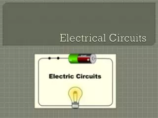
BASIC CIRCUIT CONSTRUCTION 1. Power Source (Battery, Alternator, Generator, etc.)2. Protection Device (Fuse, Fusible Link, or Circuit Breaker)3. Load Device (Lamp, Motor, Winding, Resistor, etc.4. Control (Switch, Relay, or Transistor)5. Conductors (A Return Path, Wiring to Ground
DIRECT CURRENT (DC) • Electricity with electrons flowing in only one direction is called Direct Current or DC. • DC electrical systems are used in cars.
ALTERNATING CURRENT (AC) • Electricity with electrons flowing back and forth, negative - positive- negative, is called Alternating Current, or AC. • The electrical appliances in your home use AC power.
ELECTRON THEORY • The Electron Theory states that current flows from NEGATIVE to POSITIVE. Electrons move from atom to atom as they move through the conductor towards positive
Conventional theory • also known as HOLE THEORY, states that current flows from POSITIVE to NEGATIVE. Protons or the lack of electrons (the holes) move towards the negative. (Current flow direction in Hole Theory is the opposite of that in Electron Theory.)
AUTOMOTIVE ELECTRICAL CIRCUITS In an automotive electrical circuit, one end of the wire from each load returning to the battery is connected to the vehicle body or frame. Therefore, the vehicle body or frame itself functions as a conductor, allowing current to flow though the body or frame and back to the battery. The body or frame is then referred to as the body ground (or earth) of the circuit (meaning that part of the circuit that returns the current to the battery).
Ohms Law E=IxR • 1 volt can push 1 amp through 1 of resistance • 12 volts can push 12 amps through 1 of resistance • 12 volts can push 1 amp through 12 of resistance
Ohms Law E=IxR • As Voltage increases the current will… • …increase • As Resistance increases the current will… • …decrease • As Resistance decreases the current will… • …increase
OHM'S LAW FORMULAWhen voltage is applied to an electrical circuit, current flows in the circuit. The following special relationship exists among the voltage, current and resistance within the circuit: the size of the current that flows in a circuit varies in proportion to the voltage which is applied to the circuit, and in inverse proportion to the resistance through which it must pass. This relationship is called Ohm's law, and can be expressed as follows: E = I R Voltage = Current x Resistance E Voltage applied to the circuit, in volts (V) I Current flowing in the circuit, in amperes (A) R Resistance in the circuit, in ohms In practical terms "V = I x R" which means "Voltage = Current x Resistance". 1 volt will push one amp through 1 ohm of resistance.
Voltage • Electromotive Force (EMF) • the electrical pressure that forces electrons to move from atom to atom • Voltage is present when there is a difference in electrical pressure
VOLTAGEVoltage is the electrical force that moves electrons through a conductor. Voltage is electrical pressure also known as EMF (Electro Motive Force) that pushes electrons. The greater the difference in electrical potential push (difference between positive and negative), the greater the voltage force potential.
MEASUREMENT A VOLTMETER measures the voltage potential across or parallel to the circuit. The Voltmeter measures the amount of electrical pressure difference between two points being measured. Voltage can exist between two points without electron flow
VOLTAGE LESS THANBASE UNIT BASIC UNIT LARGER THANBASE UNIT Symbol mV V kV Pronounced millivolt Volt Kilovolt Multiplier 0.001 1 1,000 VOLTAGE UNITSVoltage is measured in units called VOLTS. Voltage measurements can use different value prefixes such as millivolt, volt, Kilovolt, and Megavolt.
Amperage • The more electrons moving from atom to atom, the more current or Amperage • How many electrons (amps) move is decided by the pressure (volts) and the resistance to the flow of electrons
Amperage or Electrical Current • the Intensity of the electron movement between atoms • one amp = 6,280,000,000,000,000,000 electrons per second • Carl Sagan would say that one amp equals over six billion, billion electrons per second
Amperage • Higher Voltages (pressure) will cause more amps (electrons) to flow • Increasing the resistance to the electron movement will lower Amp flow
MEASUREMENTAn AMMETER measures the quantity of current flow.Ammeters are placed in series (inline) to count the electrons passing through it. Example: A water meter counts the gallons of water flowing through it.
AFFECTS OF CURRENT FLOWTwo common effects of current flow are Heat Generation and Electromagnetism. HEAT: When current flows, heat will be generated. The higher the current flow the greater the heat generated. An example would be a light bulb. If enough current flows across the filament, it will glow white hot and illuminate to produce light. ELECTROMAGNETISM: When current flows, a small magnetic field is created. The higher the current flow, the stronger the magnetic field. An example: Electromagnetism principles are used in alternators, ignition systems, and other electronic devices.
Define Resistance? • Resistance is the opposition to amp flow • may be caused by heat, excessive amp flow, corrosion or any insulated material • Resistance is required to perform “work”
RESISTANCEResistance is the force that reduces or stops the flow of electrons. It opposes voltage. Higher resistance will decrease the flow of electrons and lower resistance will allow more electrons to flow.
Ohms • An OHMMETER measures the resistance of an electrical circuit or component. No voltage can be applied while the ohmmeter is connected, or damage to the meter will occur. • Example: Water flows through a garden hose, and someone steps on the hose. The greater the pressure placed on the hose, the greater the hose restriction and the less water flows.
RESISTANCE FACTORS Various factors can affect the resistance. These include: LENGTH of the conductor. The longer the conductor, the higher the resistance. DIAMETER of the conductor. The narrower the conductor, the higher the resistance. TEMPERATURE of the material. Depending on the material, most will increase resistance as temperature increases. PHYSICAL CONDITION (DAMAGE) to the material. Any damage will increase resistance. TYPE of MATERIAL used. Various materials have a wide range of resistances.
Materials with High Resistance Wood Rubber Plastics Glass These materials have many electrons in their outer “valence” electron orbit. It takes tremendous pressure (Voltage) to move electrons between these atoms
LOADS The illustration below has a horn in place of the lamp. Any device such as a lamp, horn, wiper motor, or rear window defogger, that consumes electricity is called a load. In an electrical circuit, all loads are regarded as resistance. Loads use up voltage and control the amount of current flowing in a circuit. Loads with high resistance cause less current to flow while those with lower resistance allow high current rates to flow.
TYPES OF CIRCUITS Individual electrical circuits normally combine one or more resistance or load devices. The design of the automotive electrical circuit will determine which type of circuit is used. There are three basic types of circuits: • Series Circuit • Parallel Circuit • Series-Parallel Circuit
Series Circuits • A series circuit is a voltage dividing circuit
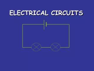
SERIES CIRCUITS A series circuit is the simplest circuit. The conductors, control and protection devices, loads, and power source are connected with only one path to ground for current flow. The resistance of each device can be different. The same amount of current will flow through each. The voltage across each will be different. If the path is broken, no current flows and no part of the circuit works. Christmas tree lights are a good example; when one light goes out the entire string stops working.
SERIES CIRCUITS • A Series Circuit has only one path to ground, so electrons must go through each component to get back to ground. All loads are placed in series. • Therefore: • 1. An open in the circuit will disable the entire circuit. • 2. The voltage divides (shared) between the loads. • 3. The current flow is the same throughout the circuit. • 4. The resistance of each load can be different
SERIES CIRCUIT CALCULATIONSIf, for example, two or more lamps (resistances R1 and R2, etc.) are connected in a circuit as follows, there is only one route that the current can take. This type of connection is called a series connection. The value of current I is always the same at any point in a series circuit
What is the total resistance? • 6 ohms • How many amps flow through R1? • 2 amps • What is the Volt drop across R1? • 4 volt • How many volts at the connection between R1 & R2 • 8 volt
Amp flow is determined by the TOTAL resistance • All amps flow through every resistor (when in series) • As amps flow through a resistor Voltage (pressure) is used up……(voltage drop) • The sum of the individual voltage drops equal the source voltage
In the following circuit, assume that resistance R is 2 and voltage V that is applied to it is 12 V. Then, current I flowing in the circuit can be determined as follows:
This law can also be used to determine the voltage V that is needed to permit current I to pass through resistance R: V = I x R (Voltage= Current x Resistance).
In the following circuit, assume that a voltage V of 12 V is applied to the circuit and current I of 4 A flows in it. Then, the resistance value R of the resistance or load can be determined as follows:
Resistance R0 (a combination of resistances R1 and R2, which are connected in series in the circuit as illustrated) and current I flowing in this circuit can be determined as follows:
Parallel Circuit • A parallel circuit is an amperage dividing circuit
PARALLEL CIRCUIT • A parallel circuit has more than one path for current flow. The same voltage is applied across each branch. If the load resistance in each branch is the same, the current in each branch will be the same. If the load resistance in each branch is different, the current in each branch will be different. If one branch is broken, current will continue flowing to the other branches.
PARALLEL CIRCUITS A Parallel Circuit has multiple paths or branches to ground. Therefore: • 1. In the event of an open in the circuit in one of the branches, current will continue to flow through the remaining. • 2. Each branch receives source voltage. • 3. Current flow through each branch can be different. • 4. The resistance of each branch can be different.
PARALLEL CIRCUITIn parallel connection, two or more resistances (R1, R2, etc.) are connected in a circuit as follows, with one end of each resistance connected to the high (positive) side of the circuit, and one end connected to the low (negative) side. Full battery voltage is applied to all resistances within a circuit having a parallel connection.