Download
1 / 10
100 likes | 203 Vues
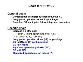
Goals for HHFW CD. General goals Demonstrate unambiguous non-inductive CD Long pulse operation at low loop voltage Establish CD scaling for future integrated scenarios Specific goals Increase CD efficiency Higher T e (more power) and lower k || (?) Establish T e , n e , k || scaling

E N D
Goals for HHFW CD • General goals • Demonstrate unambiguous non-inductive CD • Long pulse operation at low loop voltage • Establish CD scaling for future integrated scenarios • Specific goals • Increase CD efficiency • Higher Te (more power) and lower k|| (?) • Establish Te, ne, k|| scaling • Long pulse operation at low (~0) loop voltage • CD in SN and DN configurations • CD in H-mode • High beta operation (off-axis CD?) • CD with NBI • Minimize trapped electron losses (?)
Problems encountered last year • Power limitation • Noise generation and pickup increased with power • Improved shielding (Swain/Wilson RF Noise XMP) • Voltage limitation • Feedthrough modification (Wilson 6 MW XMP 026) • Transient conditions prevented long pulse operation • Central temperature collapse (MHD activity) • Wilson Large plasma XMP 027 • No current profile measurements • MSE being commissioned
0.18 V 0.15 V 0.22 V 0.22 V Current drive efficiency (normalized for density) is higher for k|| = 3 m-1 than for 8 m-1 for similar Te k|| = 7.6 m-1, neL = 1.2e19 m-3, Te = 1.4 keV k|| = 3 m-1, neL = 2.5e19 m-3, Te = 1.2 keV ICD/PRF = 0.05 A/W gFW = ICD<ne>R/PRF = 0.034 x 10¹⁹ A • m-2/W ICD/PRF = 0.03 A/W gFW = 0.043 x 10¹⁹ A• m-2/W
neL, Te(0), and PRF neL PRF Te(0) Te(0) neL RF ON (counter-CD) RF ON (co-CD) dTe/dt lower for k|| = 3 m-1 k|| = 3 m-1 k|| = 8 m-1
Co-CD Counter-CD
Driven Current Profiles for k|| = 8, 3 m-1 (T. K. Mau - CURRAY) • Use discharge 107899.0391 as a reference NSTX plasma with • neo = 1.12x1013 cm-3, Teo = 1.48 keV, Ti/Te = 0.68, b = 2.41% • Teo is varied without change in neo and profiles.
Scaling of Calculated CD Efficiency with Temperature • I/P shows a rise in value with Teo for k|| = 3 and 5.5 m-1, but is essentially flat with • Teo for k|| = 8 m-1. • This rise of I/P is weaker with Teo as k|| is increased. (Need further analysis)
Approach • Initial operation in He for better density control, later operation in D2 for integrated scenario development. • Re-establish CD at 8 m-1 first, then at 3 m -1 • 3 m -1 holds promise of better efficiency, perhaps off-axis CD. • 3 m -1 may give more problems with rf noise generation, lower plasma loading, and inefficient heating of cold electrons. • Most operation at low density to maximize driven current. Some operation at higher density to establish scaling. • Plasma may go into H-mode at higher power levels. • Most operation into SND plasmas; try DND toward the end of experiment.
SHOT LIST(50 shots, 2 days?) • 1. Power scan at –90º (k|| = 8 m-1, co-CD), low density (ne0 = 1-1.5e19 m-3), P = 2, 3, 4, 5, 6 MW (5 shots). • Power scan at +90º (k|| = 8 m-1, counter-CD), low density (ne0 = 1-1.5e19 m-3), P = 2, 3, 4, 5, 6 MW (5 shots). Power and gas feed will be adjusted to give same Te0 and ne0. Because of lower loading in counter-CD phasing, the voltage limit may be encountered at lower powers. • Power scan at –30º (k|| = 3 m-1), low density (ne0 = 1-1.5e19 m-3), P = 2, 3, 4, 5, 6 MW (5 shots). This high wave velocity wave may not couple to the initially cold electrons (although electrons were successfully heated last year at similar k||). • 3a) If there is no electron heating at –30º phasing, start at –90º phasing and switch to –30º phasing when electrons are heated. • 3b) If the loading mismatch between –90º and –30º phasing is too great to operate, run at –60º phasing, which should give peaks at both 3 and 8 m-1. • 4. Power scan at +30º phasing (or 3a or 3b) (5 shots). • 5. Repeat steps 1-4 at high density (ne0 ~ 3.0e19 m-3) (20 shots). • 6. Repeat steps 1-4 at low density (ne0 ~ 1-1.5e19 m-3) in D2 (10 shots)