Download
1 / 65
1.19k likes | 2.39k Vues
Global System for Mobile Communication (GSM): An Overview. Mobile and Wireless Networks Aslam Hayat. Contents. GSM-Introduction Architecture Technical Specifications Frame Structure Channels Call setup and registration Process Security Characteristics and features Applications

E N D
Global System for Mobile Communication (GSM): An Overview Mobile and Wireless Networks Aslam Hayat
Contents • GSM-Introduction • Architecture • Technical Specifications • Frame Structure • Channels • Call setup and registration Process • Security • Characteristics and features • Applications • Future of GSM
What is GSM ? • Global System for Mobile (GSM) is a second generation cellular standard developed to cater voice services and data delivery using digital modulation
Characteristics of GSM Standard • Fully digital system using 900,1800 MHz frequency band. • TDMA over radio carriers(200 KHz carrier spacing. • 8 full rate or 16 half rate TDMA channels per carrier. • User/terminal authentication for fraud control. • Encryption of speech and data transmission over the radio path. • Full international roaming capability. • Low speed data services (upto 9.6 Kb/s). • Compatibility with ISDN. • Support of Short Message Service (SMS).
Advantages of GSM over Analog System • Capacity increases • Reduced RF transmission power and longer battery life. • International roaming capability. • Better security against fraud (through terminal validation and user authentication). • Encryption capability for information security and privacy. • Compatibility with ISDN,leading to wider range of services
Future of GSM • 2nd Generation • GSM -9.6 Kbps (data rate) • 2.5 Generation ( Future of GSM) • HSCSD (High Speed ckt Switched data) • Data rate : 76.8 Kbps (9.6 x 8 kbps) • GPRS (General Packet Radio service) • Data rate: 14.4 - 115.2 Kbps • EDGE (Enhanced data rate for GSM Evolution) • Data rate: 547.2 Kbps (max) • 3 Generation • WCDMA(Wide band CDMA) • Data rate : 0.348 – 2.0 Mbps
bearer services GSM: Mobile Services • GSM offers • several types of connections • voice connections, data connections, short message service • multi-service options (combination of basic services)
GSM: Mobile Services cont.. • Three service domains • Telemetry Services – voice, short message service (SMS) • Data Services – • Supplementary Services GSM-PLMN source/ destination network transit network (PSTN, ISDN) TE MT TE R, S Um (U, S, R) tele services
Tele Services • Telecommunication services that enable voice communication via mobile phones • Offered services • Mobile telephony • Emergency calling • Voice messaging
Data Services • Include various data services for information transfer between GSM and other networks like PSTN, ISDN etc at rates from 300 to 9600 bps • Short Message Service (SMS) • Voice mailbox • Electronic mail
Supplementary Services Call related services : • Call Waiting- Notification of an incoming call while on the handset • Call Hold- Put a caller on hold to take another call • Call Forwarding- Calls can be sent to various numbers defined by the user • Multi Party Call Conferencing - Link multiple calls together
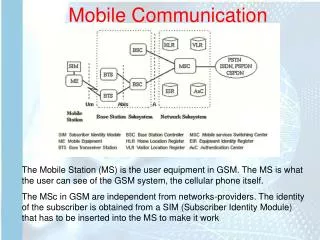
Architecture of the GSM system • GSM is a PLMN (Public Land Mobile Network) • several providers setup mobile networks following the GSM standard within each country • components • MS (mobile station) • BS (base station) • MSC (mobile switching center) • GMSC (Gateway mobile switching center) • LR (location register) • Subsystems • MSS (Mobile station subsystem) (ME and SIM) covers radio aspects • BSS (Base station subsystem): covers all radio aspects, paging etc • NSS (network and switching subsystem): call forwarding, handover, switching • OSS (operation subsystem): management of the network
cell GSM: cellular network segmentation of the area into cells possible radio coverage of the cell • use of several carrier frequencies • not the same frequency in adjoining cells • cell sizes vary from some 100 m up to 35 km depending on user density, geography, transceiver power etc. • hexagonal shape of cells is idealized (cells overlap, shapes depend on geography) • if a mobile user changes cells handover of the connection to the neighbor cell idealized shape of the cell
TE TA MT Um R S Mobile Station • Terminal for the use of GSM services • A mobile station (MS) comprises several functional groups • MT (Mobile Terminal): • offers common functions used by all services the MS offers • end-point of the radio interface (Um) • Portable, vehicle mounted, hand held device • Uniquely identified by an IMEI (International Mobile Equipment Identity) • Voice and data transmission • Monitoring power and signal quality of surrounding cells for optimum handover • Power level : 0.8W – 20 W
Mobile Station Cont.. • TA (Terminal Adapter): • terminal adaptation, hides radio specific characteristics • TE (Terminal Equipment): • peripheral device of the MS, offers services to a user • does contain GSM specific functions ,GSM version, Encryption capability frequency capability, RF power capability, sms capability • SIM (Subscriber Identity Module): • Smart card contains the International Mobile Subscriber Identity (IMSI)(15 digits) • Temporary Mobile Subscriber ID(TMSI) – per-call basis ID for security reason to avoid sending IMSI over the air • Mobile Station Roaming Number– Temporary ID for roamers • Allows user to send and receive calls and receive other subscribed services • Encoded network identification details • Location Area Identity number • Key Ki,Kc and A3,A5 and A8 algorithms • Can be moved from phone to phone – contains key information to activate the phone
Channel decoding Voice decoding De-interleaving deciphering demodulation Channel coding Voice encoding interleaving ciphering modulation amplifier Control Smart card
Base Station Subsystem (BSS) • Base Station Subsystem is composed of two parts that communicate across the standardized Abis interface allowing operation between components made by different suppliers • Base Transceiver Station (BTS) • Base Station Controller (BSC)
Base Station Subsystem (BSS) cont.. • Base Transceiver Station (BTS): • Encodes, encrypts, multiplexes, modulates and feeds the RF signals to the antenna for MS. • Frequency hopping • Communicates with Mobile station and BSC • Contains transcoder/rate adaption unit (TRAU) for speech coding and rate adaption. (placed between GSM components) • TRAU converts the 64 kbps PCM-speech into 16 kbps compressed speech [13 kbps speech + 3 kbps overhead] • Consists of Transceivers (TRX) units
Base Station Subsystem (BSS) Cont.. • Base Station Controller (BSC) • Manages Radio resources for BTS • Assigns Frequency and time slots for all MS’s in its area • Handles call set up • Transcoding and rate adaptation functionality • Handover for each MS • Radio Power control • It communicates with MSC and BTS
Tasks of Base Transceiver Station and Base Station Controller Tasks of a BSS are distributed over BSC and BTS • BTS comprises radio specific functions • BSC is the switching center for radio channels
Network Switching Subsystem(NSS) • Consist of 5 elements • MSC, HLR, VLR, AuC and EIR • MSC is the processor, the others are database units
Mobile Services Switching Center The MSC (mobile switching center) plays a central role in GSM • switching functions • additional functions for mobility support • management of network resources • interworking functions via Gateway MSC (GMSC) • integration of several databases • Functions of a MSC • Mobility management Registration Location Updating Inter BSS and inter MSC call handoff • specific functions for paging and call forwarding • mobility specific signaling • location registration and forwarding of location information • Resource allocation • provision of new services (fax, data calls) • support of short message service (SMS) • generation and forwarding of accounting and billing information
Network Switching Subsystem cont.. • Home Location Registers (HLR) • HLR contains a list of subscribers belonging to one or more MSC areas. • Permanent subscriber data including IMSI, MSISDN, roaming restriction, permitted supplementary services and authentication key. • Temporary subscriber data consist of MSRN, data related to encryption, VLR address, MSC address and roaming restriction. • HLR is usually centralized within a network. • Visitor Location Registers (VLR) • Similar to HLR but for visitors • When a roamer appears, his HLR data is transferred to the local VLR. • VLR is usually co-located with MSC.
Network Switching Subsystem cont.. • Authentication Center (AUC) • Performs authentication function for each subscriber within the system. • A key Ki kept in SIM and AuC. • Equipment Identity Register (EIR) • Records the IMEI of all subscribers in three lists. • White list ---- clean equipment • Black list ---- stolen equipment • Gray list ---- equipment with minor problems
Operation and Support Subsystem • OSS consists of two entities not fully specified in GSM. They are • Operation and Maintenance Center (OMC) • Network Management Center (NMC) • Performs alarm handling, fault management, performance management, configuration management, traffic data acquisition, activate and deactivate functions, and long term planning. Normally centralized in a network. • Implementation of these functions are operator specific.
Open Interfaces • A-Interface ---- between BSC and MSC, E1 link. • Abis-Interface ---- between BTS and BSC using LADP • (Link Access Data Protocol) protocol. • B-Interface ---- between MSC and VLR • C-Interface ---- between MSC and HLR • D-Interface ---- between HLR and VLR • E-Interface ---- between MSCs • F-Interface ---- between MSC and EIR • Um-Interface ---- between MSS and BSS.
Radio Interfaces • GSM uses both FDMA and TDMA technologies • Downlink frequency band (935-960Mhz) • Uplink frequency band (890-915Mhz) • Each band contains 124 channels of 200khz bandwidth
Characteristics of GSM Standard • Fully digital system using 900,1800 MHz frequency band. • TDMA over radio carriers(200 KHz carrier spacing. • 8 full rate or 16 half rate TDMA channels per carrier. • User/terminal authentication for fraud control. • Encryption of speech and data transmission over the radio path. • Full international roaming capability. • Low speed data services (upto 9.6 Kb/s). • Compatibility with ISDN. • Support of Short Message Service (SMS).
Advantages of GSM over Analog System • Capacity increases • Reduced RF transmission power and longer battery life. • International roaming capability. • Better security against fraud (through terminal validation and user authentication). • Encryption capability for information security and privacy. • Compatibility with ISDN,leading to wider range of services
GSM Applications • Mobile telephony • GSM-R • Telemetry System • Fleet management • Automatic meter reading • Toll Collection • Remote control and fault reporting of DG sets • Value Added Services
Future of GSM • 2nd Generation • GSM -9.6 Kbps (data rate) • 2.5 Generation ( Future of GSM) • HSCSD (High Speed ckt Switched data) • Data rate : 76.8 Kbps (9.6 x 8 kbps) • GPRS (General Packet Radio service) • Data rate: 14.4 - 115.2 Kbps • EDGE (Enhanced data rate for GSM Evolution) • Data rate: 547.2 Kbps (max) • 3 Generation • WCDMA(Wide band CDMA) • Data rate : 0.348 – 2.0 Mbps
GSM Specification MS Transmission Band : 890 – 915 MHZ BS Transmission Band : 935 – 960 MHZ 45 MHz
GSM Addressing • International Mobile Station Equipment Identity (IMEI) • International Mobile Subscriber Identity ( IMSI): • Mobile Subscriber ISDN Number ( MSISDN): • Mobile Station Roaming Number ( MSRN): • Location Area Identity (LAI): • Temporary Mobile Subscriber Identity (TMSI):
GSM – Logical channels cont.. GSM specifies two basic groups of logical channels: • Traffic channels (TCH): GSM uses a TCH to transmit user speech or data. • Two types of traffic control channels are defined • Full rate TCH (TCH/F) – provides transmission rate 13kbps for speech and 9.6, 4.8 or 2.4 for data. (to improve speech quality enhanced full rate (EFR) coders are used. • Half rate TCH (TCH/H) allows transmission of 5.6 Kb/s speech or 4.8 or 2.4 Kb/s data. • Control channels (CCH): CCHs carry signaling information to control medium access, allocation of traffic channels or mobility management.
Broadcast Control Channels • Broadcast channels (BCHs) is used by the BTS to broadcast information to the MS’s in its coverage area. • The frequency correction channel (FCCH) and the synchronization channel (SCH) carry information from the BSS to the MS. The information allows the MS to acquire and stay synchronized with the BSS. (downlink) • The broadcast control channel (BCCH) provides system information such as access information for the selected cell and information related to the surrounding cells to support cell selection and location registration procedures in an MS. (downlink)
GSM – Logical channels • Common control channel (CCCH) include following channel types: • The paging channel (PCH) is used by the network to page the destination MS in call termination. (downlink) • The access grant channel (AGCH) is used by the network to indicate radio link allocation upon prime access of an MS. (downlink) • The random access channel (RACH) is used by the MSs for initial access to the network. (slotted Aloha is used to access RACH) (uplink)
GSM – Logical channels cont.. • Dedicated Control channels - Supported in GSM for dedicated use by a specific MS. • The standalone dedicated control channel (SDCCH) is used only for signaling and for short messages. (uplink/downlink) • The slow associated control channel (SACCH) Associated with TCH or SDCCH. The SACCH is used for non-urgent procedures, mainly the transmission of power and time alignment control information over the downlink and measurement reports from the MS over the uplink. A TCH is always allocated with a control channel SACCH to transport both user information and signaling data in parallel. (uplink/downlink) • The fast associated control channel (FACCH) is used for time critical signaling such as call establishing progress, authentication of subscriber, or handover. The FACCH makes use of the TCH during a call. Thus, there is a loss of user data because the FACCH steals" the bandwidth of the TCH. (uplink/downlink) • The cell broadcast channel (CBCH) only carries the short message service cell broadcast messages, which uses the same time slot as the SDCCH. (downlink)
1 1 2 2 3 3 4 4 5 5 6 6 7 7 8 8 Downlink Delay Uplink So the MS does not have to Transmit and Receive at the same time instance!
Speech Speech Speechdecoding Speech coding 13 Kbps Channel Coding Channeldecoding 22.8 Kbps Interleaving De-interleaving 22.8 Kbps BurstFormatting Burst Formatting 33.6 Kbps Ciphering De-ciphering 33.6 Kbps Radio Interface Modulation Demodulation 270.83 Kbps GSM Operation
Frame Hierarchy and Structure • Logical frame hierarchy • 26 frame multi-frame 26 multi-frames + 51 frames or 51 multi-frames + 26 frames 2048 superframe hyperframe
GSM - TDMA/FDMA (Frame Structure) higher GSM frame structures 5 7 8 1 2 4 6 3 4.615 ms 546.5 µs = .546ms 577 µs = .577ms 935-960 MHz 124 channels (200 kHz) downlink frequency 890-915 MHz 124 channels (200 kHz) uplink time GSM TDMA frame GSM time-slot (normal burst) guard space guard space S user data tail tail user data S Training 1 3 1 57 bits 3 bits 57 bits 26 bits 148 bits +8.25 bits Every TDM Channel occupies the 200KHz carrier for 577 µsec every 4.615 mSec
GSM - TDMA/FDMA • GSM time-slot (normal burst) • Tail are all set to 0 and can be used to enhance the receiver performance. • The training sequence is used to adapt the parameters and select the strongest signal. • A flag S indicates whether the data field contains user or network control data. • GSM bursts • A normal burst for data transmission • A frequency correction burst allows the MS to correct the local oscillator to avoid interference • A synchronization burst with an extended training sequence synchronizes the MS with BTS in time. • An access burst is used for the initial connection setup. • A dummy burst is used if no data is available for a slot.
Different Transmission Bursts T coded data S train S coded data T guard 3 57 1 26 1 57 3 8.25 Normal Burst 148 bits T synch. seq. coded data T guard 68.25 8 41 36 3 Random Access Burst 88 bits guard T fixed bit sequence T Freq. Correction Burst 3 142 8.25 3 148 bits guard coded data coded data T synch. seq. T Synchronization Burst 3 39 64 39 3 8.25 148 bits
T coded data S training S coded data T guard 8.25 3 57 1 26 1 57 3 148 bits Normal Traffic Bursts • T = all-zero bits to indicate the start and the end of the • burst. • Data = The two 57-bit coded data belong to two different speech frames. • S = Stealing Flag to separate data from the training sequence. • Training = A mid-amble synch and training sequence (5-16-5) for channel adaptive equalization. Also separates two data groups • Guard time = Guard time (approx. .031 msec)
T synch. seq. coded data T guard 8 41 36 3 68.25 88 bits Random Access Burst • 8-bits Tail: all-zero bits to indicate the start and the end of the • burst. • 41-bits Synchronization: The synchronization sequence has the same significance as the training sequence. • 36-bits Coded Data: This is a short message containing data required for synchronization. • 68.25-bits Guard time : Very long guard time to account of an initial differential delay over large cell (up to 75 km one way or 35 km two-ways).
guard T fixed bit sequence T 3 142 3 8.25 148 bits Frequency Correction Burst • 3-bits Tail: all-zero bits to indicate the start and the end of the burst. • 142-bits Fixed Sequence: This is an all-zero sequence [000000…]. This sequence causes the GMSK modulator to produce a spectral line for easy frequency tracking. • 8.25-bits Guard time: Guard time identical to the one used in the normal transmission burst.
guard coded data coded data T synch. seq. T 3 39 64 39 3 8.25 148 bits Synchronization Burst • The synchronization burst has a structure similar to the normal burst. • 3-bits Tail: all-zero bits to indicate the start and the end of the burst. • 64-bits Synchronization: a known sequence for time • synchronization. • 39-bits Coded Data: The Base Station Information Code (BSIC), the Base station Color Code (BCC) and the National Color Code (NCC).(unknown) • 8.25-bits Guard time : Guard time identical to the one used in the normal transmission burst.
Training Sequence (Mid-Amble) 148 bits T coded data S training S coded data T gap 8.25 26 3 57 1 1 57 3 12 13 14 15 16 1 2 3 4 5 6 7 8 9 10 11 12 13 14 15 16 1 2 3 4 5 The 16-bit signature sequence is unique to the base station