Download
1 / 38
380 likes | 507 Vues
SPIE Smart Structures/NDE • San Diego, Mar 10, 2010. Photonic crystals for distributed strain measurements. Daniele Zonta 1 , Andrea Chiappini 2 , Alessandro Chiasera 2 , Maurizio Ferrari 2 ,

E N D
SPIE Smart Structures/NDE • San Diego, Mar 10, 2010 Photonic crystals for distributed strain measurements Daniele Zonta1, Andrea Chiappini2, Alessandro Chiasera2, Maurizio Ferrari2, Matteo Pozzi1, Lorenzo Battisti1, Matteo Benedetti3 1-DIMS - University of Trento – Italy 2-CNR-IFN, Istituto di Fotonica e Nanotecnologie, CSMFO Lab. 3-DIMTI, University of Trento
outline • motivation • what is a Photonic Crystal? • producing a Photonic Crystal • experimental validation • conclusions
motivation • the strong drive to exploit wind energy has recently led to new types of location for wind turbine installations being considered, including mountain regions • such locations are bound to be more critical, because of the more severe weather and wind conditions Drewry and Georgiou "A review of NDT techniques for wind turbines" NDT.net (2007).
motivation • a major concern is the reliability of the supporting structures in the life-long period • recent failures of lighting towers due to fatigue have raised questions as to the robustness and safety of the existing inventory of similar structures • small cracks gradually develop due to wind-induced cyclic loads and eventually the cracks with highest stress concentration propagate, occasionally resulting in a catastrophic failure Connor and Hodgson, [Field Instrumentation and Testing of High-Mast Lighting Towers in the State of Iowa], (2006).
motivation • the reliability of the structures supporting the wind turbines can be enhanced via the adoption of permanent instrumented monitoring • an efficient sensing system provides the owner with a real-time damage estimate and allows easy maintenance in order to prevent failure • the system should allow early recognition of the micro and macro crack patterns induced by fatigue load
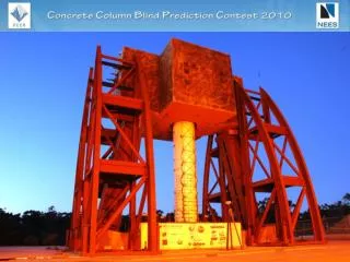
case study • prototype mini wind turbine • erected at the Trento Experimental Wind Farm • suitable for installation in mountain regions • two bladed downwind turbine • rated power 11kW • diameter of the rotor 13m • tower is 18m tall, made in three segments connected with bolted joints • connection flanges are welded to tubular profiles
case-study • prototype mini wind turbine • erected at the Trento Experimental Wind Farm • suitable for installation in mountain regions • two bladed downwind turbine • rated power 11kW • diameter of the rotor 13m • tower is 18m tall, made in three segments connected with bolted joints • connection flanges are welded to tubular profiles
numerical models • A first FEM predict the global response of the base of the tower under various environmental conditions • The model accounts for the • gust wind loads • dimamic effect effects on the blades and the rotor and on the tower itself.
numerical models of fatigue cracks • a second FEM details the behaviour of the tower about the base connection • 3D elements used • the strain field calculated with the global model is assigned as inputs to the local FEM • various crack scenarios considered
strain field around a fatigue crack • the strain field due to a crack is inhomogeneous • high concentrations around the crack tips and a specific pattern of stress increment and release • we need a distributed strain sensor capable measure the strain field!
outline • motivation • what is a Photonic Crystal? • producing a Photonic Crystal • experimental validation • conclusions
what is a photonic crystal? • produced of colloidal spheres in solution, organized into a 3-dimensional crystalline lattice • the size of the spheres and their polydispersivity are such that the crystal acts as a narrow-band mirror (it reflects or transmits only a specific wavelength range) • by an appropriate selection of the optical properties, the stop bands can be set in the visible range.
Bragg’s law the reflecting behavior of the PC can be express by the modified form of Bragg's law. where • λ is the free-space wavelength of the light • d is the inter-planar spacing • neff is the effective refractive index l l l l
theoretical sensitivity to strain light source light detector Initial configuration: q elastometer d0 polystyrene sphere support Dl e x= axial elongation Strained configuration: transversal contraction d(e) Dl l • When an axial strain is applied to the PC, the inter-planar spacing is modified by the transversal contraction. Hence the initial value d0 is reduced to d(e) depending on the applied strain value e. • This effect changes the reflectance properties of the PC, and particularly the wavelength peak in reflection.
theoretical sensitivity to transversal strain Bragg’s law: crystal n sensitivity to transversal strain: support ns transversal strain of crystal to in-plane strain of the support:
theoretical sensitivity to strain applying an axial load: crystal n support ns sensitivity to axial strain:
outline • motivation • what is a Photonic Crystal? • producing a Photonic Crystal • experimental validation • conclusions
production of PC • we produced crystal with polystyrene spheres (PSs) embedded in a poly-dimethylsiloxane (PDMS) elastomer • The fabrication process includes 3 steps: 1- production of the polystyrene spheres will form the opal structure; 2- deposition of the spheres in a lattice structure on the support; 3- infiltration of the crystal with an elastomer.
step 1: production of the nano-spheres stirrer temperature controller condenser • mix of • styrene • water • surfactant (SDS) • a polymerization initiator (K2S2O8) • controlled temperature and stirring speed • the PSs produced with a diameter of about 230nm to obtain a suitable PC color; • the size can be modified by applying a different fabrication protocol
step 2: deposition on the substrate • A highly mono-dispersed PS suspension is deposited on a Viton substrate of size 50x15x1mm. • the substrate is placed vertically into the water suspension • in oven at constant temperature of 50°C for two days
step 2: deposition on the substrate • crystallization is initially driven by strong attractive capillary forces acting between particles at the drying front • This effect drives particles to aggregate in layers and creates a porous structure with high specific surface area. • The large surface area facilitates solvent evaporation. The thickness of the PC is in the order of 10mm.
step 3: infiltration • the lattice is infiltrated with PDMS (poly-dimethylsiloxane) • after infiltration the PDMS is cured for 4 hours at 65°C • then, the excess elastomer is peeled-off from the crystal • several infiltration cycles were necessary to completely fill the voids between the PS spheres • before any re-infiltration step the sample is swollen in a silicone fluid.
result • assuming that the PSs are in contact, theory predicts a value of reflected peak l=550nm (=green) • The unstressed PC appears red while it is not stressed (l = 650nm), and turns green as a tensile strain is applied. • the actual color of the PC shows that the PSs are separated by the elastomer, (d is larger than their diameter)
outline • motivation • what is a Photonic Crystal? • producing a Photonic Crystal • experimental validation • conclusions
experimental validation • the strip is fastened to two micrometric linear stages • the diffraction characteristic of the PC is recorded using a spectrometer, composed by a light source, a light receiver and a spectrum analyzer • the probe is kept perpendicular to the strip • the area of the PC inspected by the device is about 4mm2 spectrometer light source light detector anchorage photonic crystal linear stage
set-up probe for light source and detector anchorage linear stage photonic crystal
specimen 1: l0=581nm [me]
specimen 1 [me]
specimen 1 [me]
specimen 1 [me]
specimen 1 [me]
specimen 1 [me]
specimen 1 [me]
experimental performances • sensitivity to strain: -288 pm/me • inverse sensitivity 3.47 me/pm • resolution of the reflected peak ~100 pm • instrumental resolution ~350 me • max measurable elongation: >150 me [= 15%] • to appreciate a change in color: Dl>10 nm >35 me [= 3.5%] these performance can be improved!
PCs vs. FBGs Photonic crystal • resolution of the reflected peak in the order of ~100pm (inspected area of 4mm2) • reflected band depends on the transversal strain • works in the visible (l0~400-600 nm) FBG • width of the reflected peak in the order of ~20pm (for a 20mm-long FBG) • the grating is deformed directly by the strain of the support • normally works in the infrared (l0~1550 nm)
concluding remarks • the laboratory experiment demonstrates that the fabrication of a distributed strain sensor based on PC is feasible • the resolution obtained so far is insufficient for civil applications • appropriate selection of the diameter of the spheres and of the swelling process can improve the resolution • compared with Fiber Bragg Grating, the instrumental resolution of PCs is much lower • however, in order to recognize fatigue damage it is essential to identify the planar strain field around cracks • PC can be used as a distributed sensor to reconstruct the strain field
acknowledgments Thank you for your attention! This work was carried out within the follwing projects: • PAT-CRS2007 • PAT FaStFal 2007-2010 • COST MP0702 Special thanks to: • Cristina Armellini (CNR-IFN) • Roberto Fedrizzi (DIMS-UniTN) • Vigilio Fortanari and Daniele Laner (DIMTI-UniTN)