Download
1 / 15
150 likes | 263 Vues
This document presents key methodologies and best practices for implementing Real-Time Networks (RTN) in geospatial surveying. It covers essential components such as reference frames, use of Continuous Operating Reference Stations (CORS), RTN processing techniques, and data transmission formats like RTCM. The materials discuss the Single Baseline approach versus Network approaches, Virtual Reference Station (VRS) methods, Master-Auxiliary Concept (MAC) strategies, as well as correction generation, interpolation, and quality control measures in precise positioning applications.

E N D
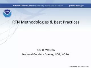
RTN Methodologies & Best Practices Neil D. Weston National Geodetic Survey, NOS, NOAA Silver Spring, MD July 31, 2013
RTN Basics City limits City limits 100 Ref. Ref. 100 Ref. * * Northing (km) Northing (km) Ref. Ref. 0 0 Easting (km) 0 Easting (km) 100 0 100 Single baseline approach Network approach
RTN Basics • Reference frame – adopt latest realization of NAD 83 (NAD 83 2011 epoch 2010.00) • CORS + RTN – include a few CORS in the RTN • Adjustments • Constrain CORS that are included • Base station monitoring • Process data periodically • Monitor coordinates over time • Base station information • Coordinates, velocities, epoch
RTN Basics and Formats • Receiver collection rate – minimum 1Hz • Data formats • Proprietary • Open standard • Compatibility • RTCM SC-104 • Only true ‘open’ protocol • RTCM-2.1 Added RTK messages for dm levels at short distances • RTCM-2.2 Expanded for differential operations with GLONASS
RTCM Formats • RTCM-2.2, 2.3 RTK operations providing cm- level performance at short distances • RTCM-3.x More efficient; support RTK operations (GPS+GLONASS); network correction message • Common message types 2.x • Type 18, 20 – RTK uncorrected carrier phase data and carrier phase corrections • Type 19, 21 – RTK uncorrected pseudo-range measurements and appropriate range corrections • Common message types 3.x • 1004 – full observables • 1005 – reference station coordinates • 1007 – antenna description
Network RTK Processing Techniques & Applications • Virtual Reference Station – VRS • Area-Parameter Correction – FKP • Master-Auxiliary Concept – MAC • Grading, utilities, pipelines, roads • Landscaping, cadastral surveys, mapping
Area Correction Parameters - FKP • Network described using coefficients for a surface • Parallel surface with baselines less than 100 km • Reference station at the center of the “surface” • Software in rover receiver does the interpolation of corrections • Error information is provided for quality control and analysis • Single and bi-directional communications
Virtual Reference Station - VRS • VRS techniques is currently the most popular • Requires bi-directional communications • VRS observations constructed • Rover approx. position to NRTK center • Rover solution based on range between VRS and rover • VRS kept to preserve ambiguities
Virtual Reference Station - VRS Ref Sta. NRTK Center Ref Sta. j Rover VRS Sta. i Ref Sta.
Master Auxiliary Concept - MAC • Rover position (NMEA) to processing center • Processing center chooses a master station – usually closest ref. station • Auxiliary stations are chosen from a 70 km catch circle • Rover receives MAC corrections via RTCM • Rover decides on method of interpolation of corrections and how the position is determined – double difference, for example
Master Auxiliary Concept - MAC Aux k4 Auxiliary k1 Master j Rover 70 km Aux k2 Aux k3
RTK Processing Network RTK Processes Correction Generation Correction Interpolation Correction Transmission Network Ambiguities Network Corrections Linear Interpolation Surface Modeling Grid-based Parameters One way Comms. Two way Comms. FKP VRS State Space Observation Space Linear Combination Least Squares Co-location MAC Net Adjust
Thank You Neil D. Weston Chief – Spatial Reference System Division 301-713-3191 x 103 Neil.d.weston@noaa.gov