Download
1 / 38
380 likes | 472 Vues
Explore multi-level logic synthesis techniques for low power design, including common subexpression extraction, Binary Decision Diagrams, power estimation, design transformations, critical path reduction, and behavioral synthesis. Learn about the latest trends in this field.

E N D
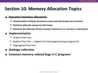
Section 10: Advanced Topics M. Balakrishnan Dept. of Comp. Sci. & Engg. I.I.T. Delhi
Multi-Level Logic Synthesis M. Balakrishnan Dept. of Comp. Sci. & Engg. I.I.T. Delhi
Objective The objective in multi-level logic synthesis is to minimize the cost under a given time-constraint (reflected as number of levels) or to perform an area-time tradeoff.
Issues in Multi-level Logic Synthesis The main issue is to factorise the multiple outputs (or sub-expressions in a single output function) with a view to extract the common sub-expressions.
Common Subexpression Extraction y2 y1 y1 y2 x1 x2 xn
Example y1 = ac + b’c + de y2 = ae’ + b’e’ + e’f t1 = (a + b’) y1 = t1c + de y2 = t1e’ + e’f
Binary Decision Diagram (BDD) For representation and manipulation of boolean functions, BDDs are used. For a given ordering of variables, the BDD representation for a function is canonical and for this reduced and ordered BDDs called ROBDDs are used.
Example: BDD y1 = a + b’c a 1 0 b b 1 0 1 0 c c c c 1 0 1 1 0 0 1 1
Example: ROBDD a 0 b 1 1 0 c 1 0 0 1
Low Power Design M. Balakrishnan Dept. of Comp. Sci. & Engg. I.I.T. Delhi
Why Low Power Design ? The need for low power design originates from two different considerations • Mobile applications: Battery life is a critical factor in making a product commercially successful • High-frequency VLSI circuits where low power dissipation is critical for circuit functionality and reliability
Technology • Universally the technology of choice for low power is CMOS • A major component of power consumption is the switching power with leakage etc. contributing insignificantly • The power dissipated by a gate is given by 0.5 Cload Vdd2 E(transitions)/ Tcyc
Issues in Low Power Design • Accurate estimations of power consumption at higher levels of design abstractions • Power reducing design transformations • Uniform distribution of power in the chip • Packaging for effective power dissipation to maintain “cool” operations
Power Estimation Power can be estimated by simulating the behavior at different levels. • Transistor level • Gate level • RTL module level • Software power estimation • Architecture level
Design Transformations • Critical path reduction • Reducing the number of operations • Reducing the transition activity • Reducing the interconnect capacitance • Operation substitution • Bit-width optimization
Critical Path Reduction • Reducing the critical path implies larger acceptable delays which in turn means a lower Vdd Delay Vdd
Transition Activity Reduction • Reduction in variation in path lengths • Coding of numbers • Coding of states and instructions
Transition Activity Reduction (contd.) d a b c b a + + + c + + d +
Operation Substitution • Some operations are very expensive in terms of power and in case it can be replaced by equivalent operations its is preferable e.g multiply by shift and add especially for multiplications with a constant
Behavioral Synthesis M. Balakrishnan Dept. of Comp. Sci. & Engg. I.I.T. Delhi
Why Behavioral Synthesis ? There is urgent need for pushing up the abstraction level at which the design can start. The reasons for this are: • As the complexity increases, this is the only way to reduce the design turn around time • An algorithmic description of the functionality is far easier to write than designing hardware
Steps in Behavioral Synthesis • Data path synthesis • Scheduling • Resource allocation (where resources include functional units, storage units, buses and interconnects) • Resource binding • Control synthesis • Clock synthesis
Scheduling • Assigning operations to control steps • This phase has a lot of influence on resource allocation as what can be done concurrently depends upon the resource availability • Complexity arises due to the range of available functional units (pipelined, multi-functional, multi-cycle etc.)
Resource Allocation • Typically manual but automating allocation algorithms are also available • FU allocation: Complexity due to the range of operators i.e. Multi-cycle, multi-function, pipelined, mixed speed operators for the same operation • Storage allocation: e.g. Registers, Memory units, Multi-port memories, Register files
Resource Binding • Examples of binding to be carried out are • Operation-operator binding • Variable-storage unit binding • Transfer-interconnect/bus binding • Binding has considerable influence on number of interconnects • Scheduling also influences binding
Control & Clock Synthesis • Generate a state machine from the control flow of the algorithm • Identify the control and status signals • Synthesize the control part • Analyze the critical path to decide on the clock period
Objectives in Behavioral Synthesis • Minimize delay time or maximize performance • Minimize cost or area • Meet constraints on area and/or performance
Recent Trends in Behavioral Synthesis • Incorporate testability conditions in synthesis • Incorporate power minimization as part of the design objective i.e. explore the design space from power considerations
System Level Design & Modeling M. Balakrishnan Dept. of Comp. Sci. & Engg. I.I.T. Delhi
Issues in System Level Design • Specification • At different levels of design • Verification • Formal verification • Simulation • Partitioning and estimation • Synthesis
Characteristics of Current Systems • One (or more) processors • Heterogeneous processor set • IP cores for critical parts of the application • Mixed hardware/software implementation • Many systems are real-time reactive systems
Specification • Functionality • Concurrency • Time/performance constraints • Interface timings • Area and power constraints
Estimation • Hardware estimate • Area(cost), performance and power estimation • Software estimate • Code size, performance and power estimation • Interface estimate • Bus bandwidth and power estimation
Partitioning • Hardware-software partitioning • Task partitioning across multiple processors • Communication partitioning across multiple buses
Synthesis • Processor synthesis (ASIPs) • Application specific instruction processor • Hardware synthesis • Behavioral as well as logic • Software synthesis • Code generation and retargetable compilers • Interface synthesis
Formal Verification • Formal verification of functional specification by proving that the implementation is equivalent to specifications. • Theorem proving techniques • Temporal logic systems
Simulation Verification by simulation though expensive but is the only widely used technique. • Cosimulation e.g. C and VHDL • Test stimulus generation