Chapter 5c: A Multi-Cycle CPU
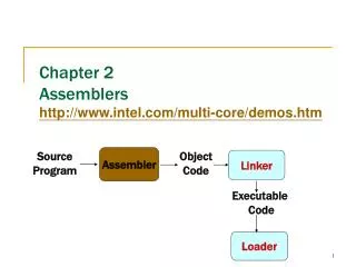
Chapter 5c: A Multi-Cycle CPU. Observations on the Single Cycle Design. The single-cycle datapath is straightforward, but... It has to use 3 separate ALU’s It has separate Instruction and Data memories Cycle time is determined by worst-case path. A multi-cycle datapath might be better

Chapter 5c: A Multi-Cycle CPU
E N D
Presentation Transcript
Chapter 5c: A Multi-Cycle CPU
Observations on the Single Cycle Design • The single-cycle datapath is straightforward, but... • It has to use 3 separate ALU’s • It has separate Instruction and Data memories • Cycle time is determined by worst-case path • A multi-cycle datapath might be better • We can reuse some of the hardware • We can combine the memories • Cycle time is still constant, but instructions may take differing numbers of cycles 5.3
The Multi-cycle idea... We can use any logic block once each cycle PC Read reg. 1 Read address Read data 1 Memory Read reg. 2 Read data Registers Result Write address Write reg Read data 2 Write data Write data Memory: Holds Instructions Holds Data ALU: Computes R-type value Computes Address Computes next PC Computes Branch Registers: Hold data values 5.4
Registers PC 0 0 Read reg num A Read address Read reg data A 1 1 Memory Read reg num B Zero Read data Result Write address 0 Write reg num 0 Read reg data B 1 Write data 1 Write reg data 2 1 3 0 Sh.Left2 signextend Multi-cycle Datapath Update PC=PC+4 Load Instruction:Need address Read Instructionfrom memory Decode,Readregisters (R-type) Start: PC Do ALU Op PC [25-21] [20-16] [15-11] 4 WriteResult reg. Branch 16 32 [15-0] Write result Store Instr. Read from Memory 5.4
Breaking instructions into cycles Mem ALU Note: Some of theseare unneeded, butthey don’t hurt! Instruction Fetch, Increment PC Decode Instruction, Access Registers Jump Reg Update PC Compute Branch Target ALU LW,SW ALU Branch R-type Compute Memory Address ALU If condition holdsupdate PC to Target Execute Instruction ALU Mem Read/Write Memory Write Register Reg Can use each major block (ALU,reg,mem)once each cycle Reg Write Register LW 5.4
Registers PC 0 0 Read reg num A Read address Read reg data A 1 1 Memory Read reg num B Zero Read data Result Write address 0 Write reg num 0 Read reg data B 1 Write data 1 Write reg data 2 1 3 0 Sh.Left2 signextend ALUcontrol Note: The control signals will be constant during each cycle, but may change during the multi-cycle instruction Multi-cycle Control Control ALUOp Inst[31-26] IorD ALUSelB MemRead ALUSelA MemWrite MemToReg RegWrite RegDest PC [25-21] [20-16] [15-11] 4 16 32 [15-0] [5-0] 5.4
Registers PC 0 0 Read reg num A Read address Read reg data A 1 1 Memory Read reg num B Zero Read data Result Write address 0 Write reg num 0 Read reg data B 1 Write data 1 Write reg data 2 1 ALUcontrol 3 0 Sh.Left2 signextend Instr. [31-0] Instr. Reg 1. Memory reads overwrite the instruction - Add Instr. Reg. - Add PCWrite Signal 2. ALU overwrites PC every cycle Issues Add PCWriteCond Signal PCWrite 3. Branches? Control PCWriteCond ALUOp Zero Inst[31-26] IorD ALUSelB MemRead ALUSelA MemWrite MemToReg RegWrite IRWrite RegDest PC [25-21] [20-16] [15-11] 4 16 32 [15-0] [5-0] 5.4
Sh.Left2 2 0 1 Registers PC 0 0 Read reg num A Read address Read reg data A 1 1 Memory Read reg num B Zero Read data Result Write address 0 Write reg num 0 Read reg data B 1 Write data 1 Write reg data 2 1 ALUcontrol 3 0 Sh.Left2 signextend Instr. [31-0] Instr. Reg On branches, the PC is alwayswritten with Zero! PCSource 28 26 Concat. Issues 32 PCWrite Control 4 PCWriteCond ALUOp Zero Inst[31-26] Inst[25-0] [31-28] IorD MemRead Logic for Jumps ALUSelA MemWrite MemToReg RegWrite IRWrite RegDest PCorPC+4 [25-21] A [20-16] ALUOut ALUSelB [15-11] B 4 MDR ALU Out: Save result of ALU for use on next cycle MDR: Save result of read for use on next cycle A, B: Save registers for use on next cycle 16 32 [15-0] [5-0] 5.4
Sh.Left2 2 0 1 Registers PC 0 0 Read reg num A Read address Read reg data A 1 1 Memory Read reg num B Zero Read data Result Write address 0 Write reg num 0 Read reg data B 1 Write data 1 Write reg data 2 1 ALUcontrol 3 0 Sh.Left2 signextend Instr. [31-0] Instr. Reg Cycle 1 All instructions PCSource 28 26 Concat. Instruction Fetch 32 0 1 x PCWrite Control 4 PCWriteCond 0 ALUOp Zero Inst[25-0] [31-28] Inst[31-26] 0 IorD MemRead 1 1 x 0 x 0 ALUSelA MemWrite MemToReg RegWrite IRWrite RegDest PCorPC+4 0 [25-21] A [20-16] ALUOut ALUSelB 1 [15-11] B 4 IorD=0MemRead=1MemWrite=0IRWrite=1ALUSelA=0 ALUSelB=1 MDR ALUOp=0PCWrite=1PCSource=0RegWrite=0 16 32 [15-0] [5-0] 5.4
Cycle 2 All instructions Sh.Left2 2 0 1 Registers PC 0 0 Read reg num A Read address Read reg data A 1 1 Memory Read reg num B Zero Read data Result Write address 0 Write reg num 0 Read reg data B 1 Write data 1 Write reg data 2 1 ALUcontrol 3 0 Sh.Left2 signextend Instr. [31-0] Instr. Reg PCSource 28 26 Concat. Instr. Decode/Reg. Fetch 32 x 0 0 PCWrite Control 4 PCWriteCond 0 ALUOp Zero Inst[25-0] [31-28] Inst[31-26] 0 x IorD MemRead x 0 0 x 0 ALUSelA MemWrite MemToReg RegWrite IRWrite RegDest PCorPC+4 0 [25-21] A [20-16] ALUOut ALUSelB 3 [15-11] B 4 MDR MemRead=0MemWrite=0IRWrite=0ALUSelA=0 ALUSelB=3 ALUOp=0PCWrite=0PCWriteCond=0RegWrite=0 16 32 [15-0] [5-0] 5.4
Sh.Left2 2 0 1 Registers PC 0 0 Read reg num A Read address Read reg data A 1 1 Memory Read reg num B Zero Read data Result Write address 0 Write reg num 0 Read reg data B 1 Write data 1 Write reg data 2 1 ALUcontrol 3 0 Sh.Left2 signextend Instr. [31-0] Instr. Reg Cycle 3 R-Type x PCSource 28 26 Concat. R-type Execution 32 0 PCWrite 0 Control 4 PCWriteCond 2 ALUOp Zero Inst[25-0] [31-28] Inst[31-26] x IorD MemRead x 0 0 x 0 0 ALUSelA MemWrite MemToReg RegWrite IRWrite RegDest PCorPC+4 1 [25-21] A [20-16] ALUOut ALUSelB 0 [15-11] B 4 MemRead=0MemWrite=0IRWrite=0ALUSelA=1 ALUSelB=0 MDR ALUOp=2PCWrite=0PCWriteCond=0RegWrite=0 16 32 [15-0] [5-0] 5.4
Sh.Left2 2 0 1 Registers PC 0 0 Read reg num A Read address Read reg data A 1 1 Memory Read reg num B Zero Read data Result Write address 0 Write reg num 0 Read reg data B 1 Write data 1 Write reg data 2 1 ALUcontrol 3 0 Sh.Left2 signextend Instr. [31-0] Instr. Reg Cycle 4 R-Type x PCSource 28 26 Concat. R-type Completion 32 0 0 PCWrite Control 4 PCWriteCond x ALUOp Zero Inst[25-0] [31-28] Inst[31-26] x IorD MemRead 0 1 1 0 x 0 ALUSelA MemWrite MemToReg RegWrite IRWrite RegDest PCorPC+4 x [25-21] A [20-16] ALUOut ALUSelB x [15-11] B 4 MemRead=0MemWrite=0 RegDest=1 MDR PCWrite=0PCWriteCond=0RegWrite=1MemToReg=0 16 32 [15-0] [5-0] 5.4
Sh.Left2 2 0 1 Registers PC 0 0 Read reg num A Read address Read reg data A 1 1 Memory Read reg num B Zero Read data Result Write address 0 Write reg num 0 Read reg data B 1 Write data 1 Write reg data 2 1 ALUcontrol 3 0 Sh.Left2 signextend Instr. [31-0] Instr. Reg Cycle 3 BEQ 1 PCSource 28 26 Concat. Branch if Equal 32 0 PCWrite 1 Control 4 PCWriteCond 1 ALUOp Zero Inst[25-0] [31-28] Inst[31-26] x IorD MemRead x x 0 x 0 0 ALUSelA MemWrite MemToReg RegWrite IRWrite RegDest PCorPC+4 1 [25-21] A [20-16] ALUOut ALUSelB 0 [15-11] B 4 MemRead=0MemWrite=0ALUSelA=1 ALUSelB=0PCSource=1 MDR ALUOp=1PCWrite=0PCWriteCond=1RegWrite=0 16 32 [15-0] [5-0] 5.4
Sh.Left2 2 0 1 Registers PC 0 0 Read reg num A Read address Read reg data A 1 1 Memory Read reg num B Zero Read data Result Write address 0 Write reg num 0 Read reg data B 1 Write data 1 Write reg data 2 1 ALUcontrol 3 0 Sh.Left2 signextend Instr. [31-0] Instr. Reg Cycle 3 Jump PCSource 28 26 Concat. Jump 2 32 1 PCWrite Control 4 PCWriteCond x x ALUOp Zero Inst[25-0] [31-28] Inst[31-26] x IorD MemRead x 0 x 0 x 0 ALUSelA MemWrite MemToReg RegWrite IRWrite RegDest x PCorPC+4 [25-21] A [20-16] ALUOut ALUSelB x [15-11] B 4 MDR MemRead=0MemWrite=0 PCWrite=1RegWrite=0PCSource=2 16 32 [15-0] [5-0] 5.4
Cycle 3 LW,SW Sh.Left2 2 0 1 Registers PC 0 0 Read reg num A Read address Read reg data A 1 1 Memory Read reg num B Zero Read data Result Write address 0 Write reg num 0 Read reg data B 1 Write data 1 Write reg data 2 1 ALUcontrol 3 0 Sh.Left2 signextend Instr. [31-0] Instr. Reg x PCSource 28 26 Concat. Memory Addr. Completion 32 0 0 PCWrite Control 4 PCWriteCond 0 ALUOp Zero Inst[25-0] [31-28] Inst[31-26] x IorD MemRead 0 x 0 x 0 0 ALUSelA MemWrite MemToReg RegWrite IRWrite RegDest 1 PCorPC+4 [25-21] A [20-16] ALUOut ALUSelB 2 [15-11] B 4 MemRead=0MemWrite=0IRWrite=0ALUSelA=1 ALUSelB=2 MDR ALUOp=0PCWrite=0PCWriteCond=0RegWrite=0 16 32 [15-0] [5-0] 5.4
Sh.Left2 2 0 1 Registers PC 0 0 Read reg num A Read address Read reg data A 1 1 Memory Read reg num B Zero Read data Result Write address 0 Write reg num 0 Read reg data B 1 Write data 1 Write reg data 2 1 ALUcontrol 3 0 Sh.Left2 signextend Instr. [31-0] Instr. Reg Cycle 4 LW PCSource 28 26 Concat. Memory Read x 32 0 0 PCWrite Control 4 PCWriteCond x ALUOp Zero 1 Inst[25-0] [31-28] Inst[31-26] IorD MemRead x 0 1 x 0 0 ALUSelA MemWrite MemToReg RegWrite IRWrite RegDest x PCorPC+4 [25-21] A [20-16] ALUOut ALUSelB x [15-11] B 4 MDR MemRead=1MemWrite=0IRWrite=0 PCWrite=0PCWriteCond=0RegWrite=0 IorD=1 16 32 [15-0] [5-0] 5.4
Sh.Left2 2 0 1 Registers PC 0 0 Read reg num A Read address Read reg data A 1 1 Memory Read reg num B Zero Read data Result Write address 0 Write reg num 0 Read reg data B 1 Write data 1 Write reg data 2 1 ALUcontrol 3 0 Sh.Left2 signextend Instr. [31-0] Instr. Reg Cycle 5 LW x PCSource 28 26 Concat. Read WriteBack 32 0 0 PCWrite Control 4 PCWriteCond x ALUOp Zero x Inst[25-0] [31-28] Inst[31-26] IorD MemRead x 1 0 1 0 0 ALUSelA MemWrite MemToReg RegWrite IRWrite RegDest x PCorPC+4 [25-21] A [20-16] ALUOut ALUSelB x [15-11] B 4 MemRead=0MemWrite=0RegDest=0 MDR PCWrite=0PCWriteCond=0RegWrite=1MemToReg=1 16 32 [15-0] [5-0] 5.4
Sh.Left2 2 0 1 Registers PC 0 0 Read reg num A Read address Read reg data A 1 1 Memory Read reg num B Zero Read data Result Write address 0 Write reg num 0 Read reg data B 1 Write data 1 Write reg data 2 1 ALUcontrol 3 0 Sh.Left2 signextend Instr. [31-0] Instr. Reg Cycle 4 SW x PCSource 28 26 Concat. Memory Write 32 0 0 PCWrite Control 4 PCWriteCond x ALUOp Zero x Inst[25-0] [31-28] Inst[31-26] IorD MemRead x x 0 x 0 1 ALUSelA MemWrite MemToReg RegWrite IRWrite RegDest x PCorPC+4 [25-21] A [20-16] ALUOut ALUSelB x [15-11] B 4 MemRead=0MemWrite=1 MDR PCWrite=0PCWriteCond=0RegWrite=0 16 32 [15-0] [5-0] 5.4
Control Finite State Machine MemRead=0MemWrite=0IRWrite=0ALUSelA=0 ALUSelB=3ALUOp=0PCWrite=0PCWriteCond=0RegWrite=0 Instr. Decode/Register Fetch IorD=0MemRead=1MemWrite=0IRWrite=1ALUSelA=0 ALUSelB=1ALUOp=0PCWrite=1PCSource=0RegWrite=0 Instr. Fetch LW or SW Jump MemRead=0MemWrite=0IRWrite=0ALUSelA=1 ALUSelB=2ALUOp=0PCWrite=0PCWriteCond=0RegWrite=0 BEQ Jump Branch Execution MemRead=0MemWrite=0 PCWrite=1RegWrite=0PCSource=2 Mem. Addr.Completion R-type MemRead=0MemWrite=0ALUSelA=1 ALUSelB=0PCSource=1ALUOp=1PCWrite=0PCWriteCond=1RegWrite=0 MemRead=0MemWrite=0IRWrite=0ALUSelA=1 ALUSelB=0ALUOp=2PCWrite=0PCWriteCond=0RegWrite=0 MemRead=1MemWrite=0IRWrite=0PCWrite=0PCWriteCond=0RegWrite=0 IorD=1 LW Memory Access SW MemRead=0MemWrite=1PCWrite=0PCWriteCond=0RegWrite=0 MemRead=0MemWrite=0RegDest=1PCWrite=0PCWriteCond=0RegWrite=1MemToReg=0 MemRead=0MemWrite=0 RegDest=0PCWrite=0PCWriteCond=0RegWrite=1MemToReg=1 Memory Access R-typeCompletion Write-back 5.4
Implementing the Control • Implementing a Finite State Machine is straightforward • 10 states --> 4 flipflops • Choose binary representations for each state • Create state transition table • Map to flipflop type • Using K-maps, build a function for each control output • 50-70 Gates • Or..., Put the FSM into a computer program and trust it 5.4
Evaluation • Multi-cycle goals: • Reuse common parts • Only one ALU in the design, but more complexity • Merge the memories • Success! • Get rid of worst-case cycle time constraint • R-type: 4 cycles, Branch: 3 cycles, Jump: 3 cycles, LW: 5 cycles, SW: 4 cycles • Which is faster? Single- or Multi-cycle? • It depends on how long the cycle time is…
Single-Cycle Performance Review What major functional units are used by different instructions? R-type: Instr. FetchRegisterReadALURegisterWrite 6ns LW: Instr. FetchRegisterReadALUMemory ReadRegisterWrite 8ns SW: Instr. FetchRegisterReadALUMemory Write 7ns Branch: Instr. FetchRegisterReadALU 5ns Jump: Instr. Fetch 2ns Assume the following times: Since the longest time is 8ns (LW),the cycle time must be at least 8ns. Memory Access: 2ns ALU: 2ns Registers: 1ns
Breaking instructions into cycles 2ns Mem ALU Assume the following times: Instruction Fetch, Increment PC Memory Access: 2ns ALU: 2ns 2ns Decode Instruction, Access Registers Jump Registers: 1ns 1ns Reg 2ns Update PC Compute Branch Target ALU LW,SW ALU Branch R-type 2ns Compute Memory Address ALU 2ns 2ns If condition holdsupdate PC to Target Execute Instruction ALU Mem 2ns 1ns 2ns Read/Write Memory Write Register Reg Resulting times: Jump, Branch: 6nsR-type, SW: 8ns LW: 10ns Reg 1ns 2ns Write Register LW 5.4