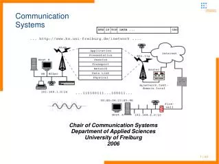
Testing Communication Systems
Testing Communication Systems. When point-to-point communication between two DTEs is not functioning, which DTE is at fault? Or which DTE is correctly following the protocol? Or is the channel OK? Many UARTs support built-in hardware facilities that permit programmers to perform software tests.

Testing Communication Systems
E N D
Presentation Transcript
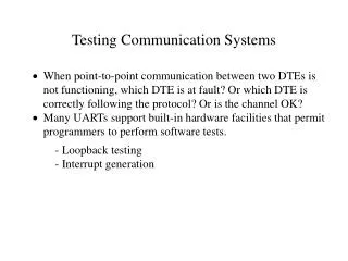
Testing Communication Systems • When point-to-point communication between two DTEs is not functioning, which DTE is at fault? Or which DTE is correctly following the protocol? Or is the channel OK? • Many UARTs support built-in hardware facilities that permit programmers to perform software tests. - Loopback testing - Interrupt generation
Loopback Testing • A loopback test causes all data normally supplied to the UART for transmission to be returned to the processor as if it has just been received. UART Output (from CPU) Serial output ... (Idle with MARKs) Input (to CPU) ... Serial input Control (disconnected) Conditions
Loopback Testing • In 8250 UART, loopback is set by writing 0x10 to Modem Control Register (addr 0x3FC for SP1 and addr 0x2FC for SP 2). 7 0 MCR loopback #define MCR_DEFN (DTR+RTS+OUT2+LOOPBK)
Generating Interrupts • Certain errors (e.g., overrun error or framing error) are caused by random or spurious events that are hard to duplicate, making it difficult to test error-handling software. • In 8250 UART, hardware interrupts can be generated through software to facilitate software testing. • Six H/W interrupts can be software generated from the Line Status Register as well as four from the Modem Status Register. • These interrupts are caused by writing to any of the corresponding status bits in the LSR and the having the UART in loopback mode.
7 6 5 4 3 2 1 0 Data Ready Overrun error Parity error Framing error Break detected Transmit holding register empty Testing Overrun-error Handling S/W 1. Turn loopback on (port 0x2FC). 2. Write 0x02 to the LSR (port 0x2FD). 3. A line status interrupt is generated by UART, causing control to be passed to the interrupt handler. 4. IIR = 0x06 , LSR = 0x02 . 5. Interrupt is serviced and cleared. LSR
UART Interrupts - Interrupt identification register indicates the cause of the interrupt. Interrupt identification register 7 6 5 4 3 2 1 0 IIR Interrupt 6 Receive line status (overrun, parity error, etc.) 4 Received data available 2 TX holding Reg. empty 0 Modem status change Interrupt pending Interrupt id (b0) Interrupt id (b1)
Channel-Monitoring Tools • Break-Out Box • Line Analyzer - indicate (by LED) which signals on each of the different pins/lines between two DTEs are active. - show the data that is being transmitted on the communication channel.
Commkit Line Analyzer - PC A acts as a line analyzer to monitor traffic between PC 1 and 2. - Basic operations: 1. Read a byte from either serial port. 2. Display the byte. 3. Forward the byte on to the other port. - Bytes from different serial ports are distinguished. - Implemented in three three parts (analyzer.c): 1. Interrupt handlers 2. Display/control process 3. Character-forwarding software A 2 1 Need 2 serial ports
Message Flow sp1_ih() sp2_ih() clk_ih() do_analyzer( ) kb_ih() sp1_ih() sp2_ih()