Download
1 / 16
160 likes | 181 Vues
Learn how to connect the MCP3008 A/D converter to the Raspberry Pi using SPI pins. Understand the communication process, accessing the MCP3008, and converting digital data. Sample code provided.

E N D
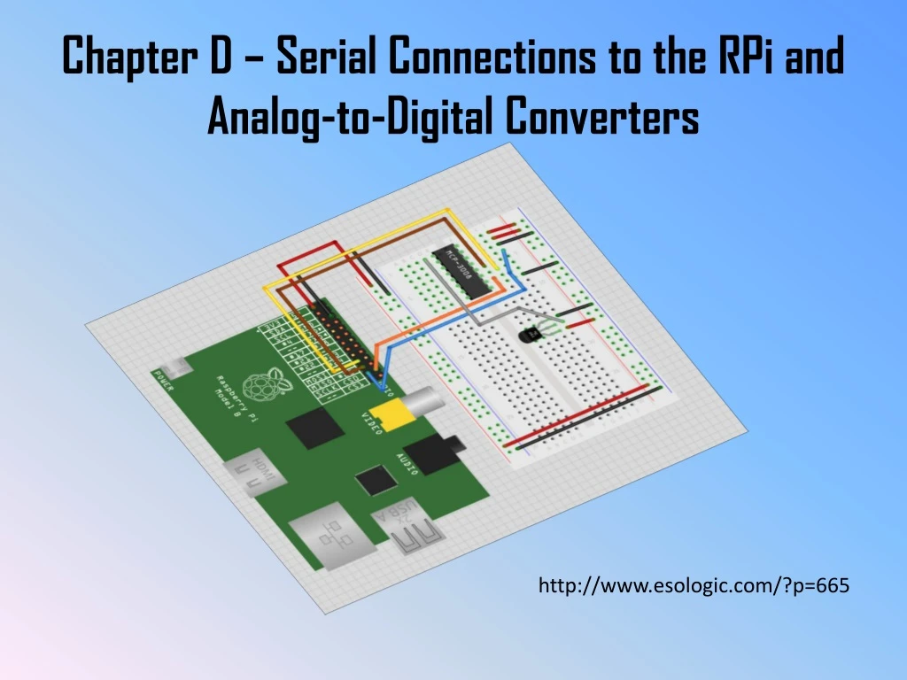
Chapter D – Serial Connections to the RPi and Analog-to-Digital Converters http://www.esologic.com/?p=665
The MCP 3008 A/D converter • The MCP3008 has 8 analog inputs that can all be converted to digital values between 0 and 1023 (there are 10 bits of data), and: • uses sample and hold circuits to get the data • runs on voltages between 2.75 – 5.5 V • can transfer between 75 – 200 ksps • transfers data with the SPI protocol (0,0 or 1,1)
SPI pins on the RPi GPIO • Pin 19 Master Out / Slave In • Pin 21 Master In / Slave Out • Pin 23 Serial Clock • Pin 24 Chip Enable 0 • (or Chip Select 0) • Pin 26 Chip Enable 1 (or Chip Select 1)
More on the RPi SPI pins • The Serial clock controls the speed at which serial data is transferred between the RPi and the A/D. • The serial clock period is an integer multiple of the CPU clock period. You can change the multiple between 2 and 65,536 (by powers of 2). This must be adjusted for the speed of the A/D. • The Chip select lines are used to select an A/D. With two CS/CE lines, you could select from four serial devices. A device is selected when the Chip select is low (usually).
More on the RPi SPI pins • The Master Out / Slave In is normally the line over which data will be sent from the RPi to the A/D. This line will tell the selected A/D : • to start sending data • to chose between single-line mode and differential input mode. • from which of its 8 analog inputs to send data. • The Master In / Slave out is normally the line that will be receiving data from the A/D.
Accessing the MCP3008 A/D converter • VDD Supply voltage • VREF Reference voltage • AGND analog ground • CLK clock input • Din data in • Dout data out • CS/SHDN chip select • DGND digital ground • CH0 – CH7 analog inputs
A/D – RPi connections MCP 3008RPiRPi Pin# • VDD 3.3V 01 • VREF 3.3V 01 • AGND GROUND06 • CLK SCLK 23 • Din MOSI 19 • DoutMISO 21 • CS/SHDNCE024 • DGNDGROUND06 • CH0 – CH7goes to temperature sensor!
Communication process • CE0 must be low • RPi must send 5 bits of information to A/D on MOSI: • A “1” to indicate that data should be sent • A 0 or 1 to indicate whether differential data should be sent, or single line data, respectively (we want 1) • Three bits to indicate which analog input should be digitized and read: • 000 for CH0 010 for CH2 100 for CH4 • 001 for CH1 011 for CH3 …111 for CH7
Communication process, ctd • So, to read Channel zero, we need to send “11000”. • This can appear anywhere in a byte, so: • 00011000 = 0x18 we will use this one • 00110000 = 0x30 • 01100000 = 0x60 would this one be better? • 11000000 = 0xC0
Communication process, ctd • Thus, sample channel calls are: • CH0 00011000 = 0x18 • CH100011001= 0x19 • CH200011010= 0x1A • CH3 00011011 = 0x1B • CH600011110= 0x1E • CH700011111= 0x1F
Converting the digital data • The A/D has a precision of 10 bits, or 210=1024 • The 10 bits are divided between two bytes (dc=don’t care): data[1] data[2] • We are going to right shift B3 – B0 4 bits: data[1] data[2] • We are going to mask 6 bits: data[1] data[2] • We will left-shift the left byte 4 spaces by multiplying by 16 and add the right byte in an integer (2 bytes long): data_int
Sample code for the MCP3008 // mcp2835 example #2 // using a temperature sensor to measure ambient temp // working with the MCP3008 A/D converter // #include <bcm2835.h> #include <stdio.h> // // codes needed for the eight analog channels #define ANALOG0 0x18 #define ANALOG1 0x19 #define ANALOG2 0x1A #define ANALOG3 0x1B #define ANALOG4 0x1C #define ANALOG5 0x1D #define ANALOG6 0x1E #define ANALOG7 0x1F
The MCP3008.c program continued int main(intargc, char **argv) { int Count, data_int; float data_voltage, temperature; char channel[4]={0,0,0,0}, data[4]; // // check for proper initialization of the GPIO // if (!bcm2835_init()) { printf("error initializing the GPIO"); return 1; } //
The MCP3008.c program continued // // Set up spi serial communication. // Slow down transfer rate (divide clock frequency by 4096). // Use CS0/CE0 to initiate data transfer (when CS0 is set to zero). // Use SPI serial interface mode 0,0 (MODE0). // bcm2835_spi_begin(); bcm2835_spi_setClockDivider(BCM2835_SPI_CLOCK_DIVIDER_4096); bcm2835_spi_chipSelect(BCM2835_SPI_CS0); bcm2835_spi_setChipSelectPolarity(BCM2835_SPI_CS0, 0); bcm2835_spi_setDataMode(BCM2835_SPI_MODE0); // channel[0]=ANALOG3; // read from analog pin3
The MCP3008.c program continued // // main loop to read data // // Send data on which channel to use and then receive 4 bytes of data. // The first two bits are DC (Don't care), then there are 10 bits of // data from MSB to LSB, then there are 10 bits of data LSB to MSB. // The rest of the bits from the MCP3008 are zero. // while(1) { bcm2835_spi_transfernb(&channel[0], &data[0], 4); // // convert to integer, voltage, temperature: the next three lines require // considerable explanation // data_int=16*(data[1] & 0x3F) + ((data[2]>>4)&0x0F); data_voltage=3.3*data_int/1024.; temperature=72.+100.*(data_voltage-0.75);
The MCP3008.c program final lines // // print out results // printf("\nData out= "); for (Count = 0; Count < 4; Count++) printf("%02X ",data[Count]); printf(" %i %f %f",data_int, data_voltage,temperature); } // //end of loop - Return SPI pins to default inputs state // bcm2835_spi_end(); return 0; }


