Transformer Vibration Analysis
280 likes | 366 Vues
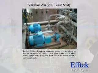
Discover the evolution of vibration analysis on transformers from inception to the present, uncovering causes and solutions for equipment failures. Learn about state-of-the-art technology, severity criteria, comparative analyses, and future advancements in this critical field.

Transformer Vibration Analysis
E N D
Presentation Transcript
Transformer Vibration Analysis By George Spencer
VIBRATION ANALYSIS on TRANSFORMERS • How we got started. • Where we are today. • What we need to do to advance.
M&D Center Substation Project • Started in 1990 at PECO Energy. • All successful diagnostic technology from Power Plant programs was applied to Transformers and Support Equipment. • Vibration, Acoustic Emission and Sound Level were considered Special Tests by most Utilities.
1990 • Lot’s of Transformers were failing, everywhere in the world.(1980-95) • Some Utilities were losing better than one percent of their system. • The average life was and still is 25 to 30 years. • Why? They were built to last a minimum of 40 years at full load. • Could it be that the equipment bolted to the transformer was causing them to fail? • Would better “At the factory” and “On the pad” acceptance testing have identified problem Transformers?
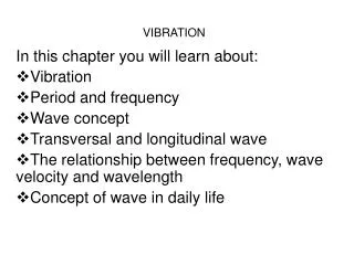
Vibration Analysis • An ideal machine would not produce any vibration at all because all energy would be channeled into the work being done. • A transformer is a device, having no moving parts. Although this is basically true, there is some movement in the core steel as the AC magnetic field reverses its direction. • Transformer coils must be rigidly blocked to prevent distortion under the stresses caused by heavy currents. • A good design will produce low levels of inherent vibration. • As equipment parts wear/age, the vibration will increase.
120Hz~0.15ips 240 360
Vibration Analysis • Properly applied, vibration analysis can detect mechanical problems before they become a threat to the integrity of the equipment. • This early detection can provide valuable lead time to resolve warranty issues with the manufacturer. • Equipment reliability, availability and useful life are also greatly improved.
Causes of Transformer Failures • Loose Windings • Deformed Windings • Load Tap Changers • Cooling Systems • Ownership • Technology Application • Factory Issues • Database and Communication
VIBRATION ANALYSIS A “STATE OF THE ART” TECHNOLOGY (As applied to rotating power plant equipment) • Early years were tough 1975-1990 • Customers demanded “Time to failure”, now it’s “how much remaining life?” • Analysts were just getting feet wet • User groups were forming (Things got better fast)
Vibration Severity Criteria for Transformers • Started with the following overall levels. • 0.25-.50 ips-…Minor • 0.50-.75 ips-… Intermediate Watch list (further investigate) • 0.75-1.0 ips-… Serious Look for oil leaks, hot metal gasses and increasing sound levels. • 1.00 ips or greater-…Critical Oil leaks, gas generation rates and hot spots.
X X X X Shell Form Eight readings ~ Approx 5 ft from “bottom of core” – 18 in. from corner 9
0.15@240 0.09@360 0.22ips Side 3R Side 3L 0.9ips Side 4L Overhead View of Transformer Side 2R Snd=78db AE=30Cts Snd=80db AE=35Cts 0.05ips Side 4R High Voltage Side Side 2L Side1R Side 1L NOTE: In addition… IR, Functional Tests and a close examination of Transformer Oil is performed.
ComparingLike Transformers • The following two transformers are in the same yard. • They are both the same age and MFG.
Vibration Analysis on Pumps Pump Data Points • Axial (Most Important) • 0.1ips or greater is recognized as a serious condition. (User group issue)
Comparing 4 normal Pumps Transformer 1A 120 Hz
What is wrong here? Transformer 1B 120 Hz
Vibration Analysis • New Concept in Recognizing Internal Condition of Transformers • Baseline when new (Trend Changes) • Document Current Condition at Load.(50% or greater) • Assess Pump Condition • High Vibration = Oil Leaks
Vibration Data • 120 Hz is the dominate frequency • Acquire baseline spectrum, document 120Hz level. Watch for increases/decreases. • Issues for user group • 120Hz goes to high level…Do we have Deformed Windings? • 120hz goes to low level and sound level increases…Loss of Blocking? • Presence of 60Hz in spectrum (Rare)…What is the cause?
What we need to do to advance. Form user group • Determine severity criteria. • Decide on Data Point Locations. (Core and Shell Form) • Agree on “C” weighted sound level data instead of the “A” weighted now used by most MFG. • Evaluate DGA data for relationship between “Hot Metal Gas” generation and vibration levels. • Recommend vibration data be acquired as part of factory acceptance testing.
What we need to do to advance. (Cont) • Communicate to the Manufacturer what the acceptable levels for Vibration and Sound Level are. • Perform SFRA analysis on various Transformers with abnormal spectrums.