
MIST
MIST. Direct Current. 02-02-2010 Dept of Aeronautical Enggineering S.M.M. Rahman. Limitations: Transmission Loss No Amplification Power Distribution Lim. Expensive. MIST. DC or AC ?.

MIST
E N D
Presentation Transcript
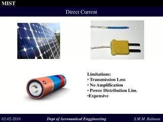
MIST Direct Current 02-02-2010 Dept of Aeronautical Enggineering S.M.M. Rahman • Limitations: • Transmission Loss • No Amplification • Power Distribution Lim. • Expensive
MIST DC or AC ? 02-02-2010 Dept of Aeronautical Enggineering S.M.M. Rahman ”A different type of Power System is needed to overcome the limitations” Solution? Should we try with Alternating Current (AC) system?
MIST Generation of Alternating Current 90 180 270 360 02-02-2010 Dept of Aeronautical Engineering S.M.M. Rahman “the light bulb still lights but the electron current is constantly reversing directions” “The direction of current flowing in a circuit is constantly being reversed back and forth”
MIST Alternating Current 02-02-2010 Dept of Aeronautical Engineering S.M.M. Rahman Oscillatory Current An oscillatory current is a current which alternately increases and decreases In magnitude with repect to time according to some definite law time Periodic Current A periodic current is a oscillating current the values of which at equal interval i= I0+ I1 sin (ωt+α1)+ I2 sin (2ωt+α2)+......... Alternating Current Alternating current is a periodic current, the average of of which over a period is zero i= I1 sin (ωt+α1)+ I2 sin (2ωt+α2)+.........
MIST Period and Frequency Period(T) Time(t)/angle(α) 02-02-2010 Dept of Aeronautical Engineering S.M.M. Rahman The time for one complete cycle is defined as Period ( T ). Freqency ( f )is the number of cycles per second frequency, f = 1/T A complete cycle corresponded to 2π electrical radians or 360 degrees. Therefore the Angular Velocity, ω = 2 π/T = 2 πf We use 50 Hz AC sytem
MIST Alternating Current/Voltage - Sine Wave Im t ωt = π ωt = 2π 02-02-2010 Dept of Aeronautical Engineering S.M.M. Rahman Triangular wave Square wave ”In practice, many AC waves approximate a sine wave very closely and therefore its calculations are based on sine waves” i= Im sin ωt or i=Im sinα
MIST Phase i= Im sin (ωt+Ө) Ө phase angle 02-02-2010 Dept of Aeronautical Engineering S.M.M. Rahman ”Phase is the fractional part of a period through which time or the associated time angle ωt has advanced from an arbitrary reference” i= Im sin (ωt+Ө)represents a sine wave of current with phase angleӨ
MIST Phase Difference 02-02-2010 Dept of Aeronautical Engineering S.M.M. Rahman Applied voltage is, v = Vm sin ωt Due to nature of circuit parameters the current comes to a certain point before the voltage wave by degrees to that point, then the current can be expressed as i= Im sin (ωt+Ө)
MIST Phase Difference 02-02-2010 Dept of Aeronautical Engineering S.M.M. Rahman To further describe the phase relationship between two sine waves, the terms Lead and Lag are used. The amount by which one sine wave leads or lags another sine wave is measured in degrees. The positive maximum of the leading quantity occurs before the positive maximum of the lagging quantity
MIST Impedance Z 02-02-2010 Dept of Aeronautical Engineering S.M.M. Rahman “Electrical impedance extends the concept of resistance to AC circuits, describing not only the relative amplitude of the voltage and current, but also the relative phases” Impedance is represented by, Z∟Ө Z define the ratio of Vm to Im Ө define their relative phase difference
MIST Impedance C 02-02-2010 Dept of Aeronautical Engineering S.M.M. Rahman R Circuit L Circuit C Circuit RL Circuit RC Circuit RLC Circuit
MIST Resistive Element 02-02-2010 Dept of Aeronautical Engineering S.M.M. Rahman Applied voltage v= Vm sinωt Current i= Im sinωt Instantaneous Power is given by,
MIST Inductive Element 02-02-2010 Dept of Aeronautical Engineering S.M.M. Rahman A sinusoidal voltage is applied to a pure inductor Vm/Im= ωL and ilags v by 90 degree. Therefore, the impedance of L branch is Integrating both sides Here ωL is called inductive reactance XL= ωL = 2πfL The constant c1 will be considered to be zero, then the expression for i reduces to
MIST Inductive Element 02-02-2010 Dept of Aeronautical Engineering S.M.M. Rahman The instantaneous power delivered to the pure inductance is • The power variation is symmetrical and • The average power absorbed is equal to zero • positive and negative power exist for a purely • Inductive circuit
MIST Inductive Element 02-02-2010 Dept of Aeronautical Engineering S.M.M. Rahman The inductive element receives energy from source during one quarter of the applied voltage And returns exactly the same amount of energy to the driving source during the next one-quarter of a cycle. The energy delivered to the circuit during a quarter of a cycle is
MIST Capacitive Element C 03-02-2010 Dept of Aeronautical Engineering S.M.M. Rahman A sinusoidal voltage is applied to a pure inductor Vm/Im= 1/ωc and ileads v by 90 degree. Therefore, the impedance of C branch is Differentiating the equation with respect to time Here 1/ωC is called capacitive reactance Xc= 1/ωC = 1/2πfC
MIST Capacitive Element C 03-02-2010 Dept of Aeronautical Engineering S.M.M. Rahman The instantaneous power delivered to the pure capacitor is • The power variation is symmetrical and • The average power absorbed is equal to zero • positive and negative power exist for a purely • Inductive circuit
MIST Capacitive Element C 03-02-2010 Dept of Aeronautical Engineering S.M.M. Rahman The capacitive element receives energy from source during one quarter of the applied voltage and returns exactly the same amount of energy to the driving source during the next one-quarter of a cycle. The energy received by the capacitor during a quarter of a cycle is
MIST RL Branch 03-02-2010 Dept of Aeronautical Engineering S.M.M. Rahman Resistane R and Inductance L are connected in series and a sinusoidal sinusoidal Current Imsin ωt flows in the circuit, then
MIST RL Branch 03-02-2010 Dept of Aeronautical Engineering S.M.M. Rahman
MIST RL Branch 03-02-2010 Dept of Aeronautical Engineering S.M.M. Rahman The instantaneous power of delivered to the RL circuit is Average Power
MIST RL Branch 03-02-2010 Dept of Aeronautical Engineering S.M.M. Rahman Instantaneous power delivered to the RL branch The equation has two components, real and reactive component Instantaneous Real power Instantaneous Reactive power Real Power Reactive Power The real and reactive power may be combined to yield the volt-ampere of the circuit
MIST RLC Branch 09-02-2010 Dept of Aeronautical Engineering S.M.M. Rahman A sinusoidal current flows to the RLC series circuit The voltage accross R, L and C become The sum of the three component voltages
MIST RLC Branch 09-02-2010 Dept of Aeronautical Engineering S.M.M. Rahman
MIST RLC Branch 09-02-2010 Dept of Aeronautical Engineering S.M.M. Rahman • Inductive and capacitive branch cause exactly opposite phase • displacement of current with respect to voltage. • ωL is positive quantity and 1/ωC is negative quantity Impedance:
MIST RLC Branch 09-02-2010 Dept of Aeronautical Engineering S.M.M. Rahman i= Im sinωt and v=Vm sin(ωt+Ө) Instantanous power delivered to the RLC branch Real power delivered to the RLC branch is Reactive power delivered to the RLC branch is
MIST Effective Current and Voltage AC DC 09-02-2010 Dept of Aeronautical Engineering S.M.M. Rahman ”An alternating current which produces heat in a given resistance at the same average rate as I amperes of direct current is said to have a value of I ” The average rate of producing heat by direct current is The average rate of producing heat by AC current during one cycle is
MIST Root Mean Square Value 09-02-2010 Dept of Aeronautical Engineering S.M.M. Rahman The RMS value is the effective value of a varying voltage or current. It is the equivalent steady DC (constant) value which gives the same effect.
MIST Average Value 09-02-2010 Dept of Aeronautical Engineering S.M.M. Rahman Average value of a ac wave is zero, however, average value of a ac wave means the average of either the positive or negative loop of the wave
MIST RMS Value of a Sinusoidal Wave 09-02-2010 Dept of Aeronautical Engineering S.M.M. Rahman Root mean square value of a sinusoidal wave is 0.7 of the peak value
MIST Average Value of a Sinusoidal Wave 09-02-2010 Dept of Aeronautical Engineering S.M.M. Rahman Therefore, average value of a sinusoidal wave is 0.636 of the peak value
MIST Form Factor 09-02-2010 Dept of Aeronautical Engineering S.M.M. Rahman Form factor is the ratio of the effective voltage to the average value of the wave Form Factor= RMS Value/ Average Value
MIST Peak Factor 09-02-2010 Dept of Aeronautical Engineering S.M.M. Rahman Pure sine wave Form factor=0.707 Vm/0.636 Vm = 1.11 e = Em sin ωt + (5/12) Em sin 5ωt Form factor= 1.11 • Form factor of both waves are same • It gives no certain indication of wave shape or wave form • Give some indication of relative hysteresis loss • use in determining induced effective voltage when non sinusoidal flux • wave is present in the iron core
MIST Peak Factor 09-02-2010 Dept of Aeronautical Engineering S.M.M. Rahman Peak factor is the ratio of the maximum value to the effective value of a wave Pure sine wave Peak factor= Em/0.707Em = 1.41 e = Em sin ωt + (5/12) Em sin 5ωt Peak factor= 1.85
MIST Peak Factor 09-02-2010 Dept of Aeronautical Engineering S.M.M. Rahman • The purpose of the crest factor calculation is to give an analyst a • quick idea of how much impacting is occurring in a waveform • For dielectric test a knowledge of crest factor is required
MIST Form Factor and Crest Factor of Different Waves 09-02-2010 Dept of Aeronautical Engineering S.M.M. Rahman
MIST Vector Representation of a Sine Wave 09-02-2010 Dept of Aeronautical Engineering S.M.M. Rahman • AC computations are often based upon the assumption of sine waves • of voltage and current • It is cumbersome to handle instantaneous values in the form of equations • of the waves • Vector/ Phasor method could be used to represent sine waves • It simplifies certain kinds of calculations • The phasor/vector representations of sine functions may be manipulated • instead of the sine functions themselves to secure the desired result
MIST Vector Representation of a Sine Wave 09-02-2010 Dept of Aeronautical Engineering S.M.M. Rahman
MIST Vector Representation of a Sine Wave 09-02-2010 Dept of Aeronautical Engineering S.M.M. Rahman
MIST Vector Representation of a Sine Wave 09-02-2010 Dept of Aeronautical Engineering S.M.M. Rahman • The lengths of two the vectors represent maximum values of • the waves respectively, the resultant vector will represent the • maximum value of the two waves • Effective or rms value could be used instead of maximum values • The vector can be considered to represent effective values
MIST Vector Representation of a Sine Wave 09-02-2010 Dept of Aeronautical Engineering S.M.M. Rahman • A convanient reference axis should be established • Counterclockwise is considered the positive direction of rotation of • axis
MIST Vector Representation of a Sine Wave 09-02-2010 Dept of Aeronautical Engineering S.M.M. Rahman • For a pure resistance applied voltage is in phase • with the current • For a pure inductance circuits, the voltage drop accross • the inductor leads the current by 90 degree • For a pure capacitance circuits, the voltage drop accross • the capacitor lags the current by 90 degree
MIST Vector Representation of a Sine Wave 09-02-2010 Dept of Aeronautical Engineering S.M.M. Rahman
MIST Vector Representation of a Sine Wave 09-02-2010 Dept of Aeronautical Engineering S.M.M. Rahman