Download
1 / 32
320 likes | 356 Vues
IKON16. PSS for Instruments. Stuart Birch ICS-Protection Systems Group- Senior Engineer Personnel Safety Systems. ESS/ICS/PS 2019-02-12. PSS flow. Contents. Stakeholder Associated Equipment (SAE) Technical description. Global Hazard and risk assessment (operational) PSS Pre-start Review

E N D
IKON16 PSS for Instruments Stuart Birch ICS-Protection Systems Group- Senior Engineer Personnel Safety Systems ESS/ICS/PS 2019-02-12
Contents • Stakeholder Associated Equipment (SAE) Technical description. • Global Hazard and risk assessment (operational) • PSS Pre-start Review • Safety Plan - ESS-0469185 • V&V Plan - ESS-
Instrument TechnicalDescription • Instrument Technical Description
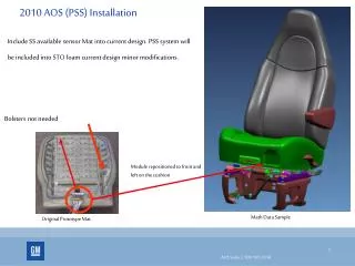
Instrument TechnicalDescription • Most up to date technical description of the instrument from the target through to the • beam stop including: • Light/neutron shutter • Bunker installations • Beamline guide equipment including: • Choppers • Collimation • Cave and cave equipment including: • Sample positions • Detectors • Jaw sets • Moving equipment • Collimators • Any other instrument permanent equipment that is used in normal operations • Please also provide: • Concept of operations • Cartoon/plan drawing showing all equipment and equipment positions
Hazard and Risk Assessments • Hazard and risk assessment.
Hazard and Risk Analysis Workshops shall be held with personnel from different groups representing the different systems involved. The system should divided into two nodes: equipment inside the bunker and equipment outside of the bunker. Classification of risk. • Classification of risk for radiological hazards shall been carried out in accordance with: • General Safety Objectives ESS-0000004 • Charter for Radiation Safety Committee ESS-0440582 • Classification of risk for non radiological hazards shall be carried out in accordance with: • Risk matrix for conventional safety ESS-0379511
Conventional Safety Matrix Likelihood Severity
Safety Plan – ESS-0469185 • Safety Plan - ESS-0469185
Safety Plan – ESS-0469185 This safety plan defines the life-cycle activities for Personnel Safety Systems (PSS). It establishes how the steps in the safety life-cycle are accomplished and ensures that the required activities during each life-cycle phase are adequately planned. • These activities range from: • Ensuring proper risk and hazard analysis, • Compliance with safety requirements, • Planning and execution of installation • commissioning to ensuring functional safety during operation. • This safety plan also defines the roles and responsibilities related to the life-cycle activities. • The development of a PSS follows IEC 61511
Standards ✓ IEC 61508 ✗ IEC 61511
Safety Plan – ESS-0469185 • Lifecycle phases • The plan describes each phase in the lifecycle • Each Phase has: • An overall objective • Inputs • Outputs • Acceptance requirements • Tools and methods • Responsibilities
Safety Plan – ESS-0469185 Lifecycle phases
Safety Plan – ESS-0469185 • Functional Safety Assessment • A FSA shall be performed to review the work carried out in the previous stage and the corresponding results at the following stages: • After safety life-cycle phase 3: Safety requirements specification • After safety life-cycle phase 4.1: Design and engineering • After safety life-cycle phase 5: Installation, commissioning and validation • In safety life-cycle phase 6: Operation and maintenance • In safety life-cycle phase 7: Modifications • At each of these stages, the external assessor shall review the documentation up to this point and evaluate the functional safety of the PSS under development.
Safety Plan – ESS-0469185 Appendices Appendix A - Initiating Event Register: The initiating event register summarizes all initiating events in relation to the hazards resulting from them and provides qualitative assessment of hazardous scenarios against a radiation and Conventional safety risk matrix. The appendix gives a step by step guide through this process.
Safety Plan – ESS-0469185 • Appendix B – Safety Integrity Level SIL. determination and Verification • details the methodology used for determination and verification of SILs during the allocation of safety functions in the safety life-cycle. • General concepts of risk reduction • Safety Integrity Level SIL • Risk targets • Layer Of Protection Analysis LOPA • LOPA for low demand safety instrumented functions SIF’s • LOPA for High demand or continuous SIF’s • Independent protection layers • Hardware reliability • Probability of failure on demand • Failure rate • Mean down time • Voting configuration • Common Cause failure
Safety Plan – ESS-0469185 • Appendix B (continued) – • Architectural Assessment Methodology • Hardware fault tolerance • Safe Failure Fraction SFF • Architectural constraints • Appendix C - Requirements formulation and naming : • Details the formulation and naming of the requirements developed in phase 3 of the lifecycle. • The requirements are to be formulated to be: • Unambiguous (Only one interpretation possible) • Traceable (Having a unique identifier) • Consistent (No conflict with other requirements) • Verifiable (It shall be possible to check whether the system meets the requirements) • Complete (No lack of relevant information) • The requirements are written statements using either “shall” “should”, where • “shall” is a mandatory statement and • “should” is an optional statement.
Verification and Validation Plan – ESS-0328060 • Verification and Validation Plan- ESS- 0328060
Verification and validation – ESS-0328060 • Prior to any operation or energization of the systems interlocked by PSS, the PSS shall be verified and validated. • It will not describe the test activities in detail, giving all complete approved test specifications and test reports. • Provides an overview of standards, required tests, reviews and assessments • When (sequence), where, who and how! • Inputs, outputs, entry criteria, acceptance criteria and roles for all: • Reviews • Tests • Tools • Methods • Functional Safety Assessments • It shall be used as an input when designing the test specifications and test reports.
Verification strategy HW and SW component tests, system integration tests, the tests planning, and documentation shall be carried out according to: • Functional safety – Safety instrumented systems for the process industry sector (IEC 61511), 2016. • Automation systems in the process industry – Factory acceptance test (FAT), site acceptance test (SAT), and site integration test (SIT) (SS-EN 62381),2012. • All documents shall be reviewed and approved by appropriate reviewers • NORA • Notified • Owner • Reviewer • Approver • Reviews (PSR, PDR, CDR, TRR) • Functional Safety Assessment • The software shall have documented code reviews • Traceability
Traceability for instrument PSS • The Initiating Event Analysis document the Overall Safety Requirements. • The Requirement Specification(s) (SRS) • The safety requirements for each SIF. • It includes specifications of both the functional and safety integrity requirements for the system. • Each test and validation report template and report shall have a traceability matrix
Hardware FAT • Verifies that the as-built hardware system meets the specified design. • Includes component test • Performed by the vendor, but it should be designed and accepted by ESS. Note: • The HWFAT follows the ESS guideline for FAT.
Hardware SAT • Verifies that the hardware system is installed as specified in its operational environment (On site). • HWSAT include the same tests as the HWFAT and some additional field device tests and a loop check.
Software verification The Software FAT follows the recommendations from IEC 61511 standard and has two stages: • Software Pre FAT - preparation for software FAT, where the software developer tests the code in test environment, mainly through simulation. • Software FAT (included in PSS SIT and FIT)
Software Pre FAT • It includes the software code review • shall include a confirmation from independent software code review that software is ready for SIT.
Site Integration Test (SIT) • The SIT verifies that installed hardware and software work together properly. • For software (A.12.5.3 in IEC 61511-2): • Performance tests • Integration-level structural tests • System-level integration tests • Tools: • Windows laptop with PLC programming tool • Multimeter for continuity tests • PSS PLCs • PSS HMI-s • Note: To reduce the risk of damaging the SAE due to repeated tests, the SAE shall be disconnected from PSS during PSS SIT.
Final Integration Test (FIT) • The FIT is a repetition of SIT whilst SAE is operational and connected to PSS. • Stakeholder associated equipment (SAE) • Equipment in that instrument PSS interlocks in order to mitigate risk associated with them.
System demonstration and handover • The demo covers the real system and the positive tests from the FIT • To prove that PSS meets the safety and operational requirements • Presented to all identified stakeholders • The stakeholders shall have access to all PSS documentation before the handover and demonstration.
Questions? Thank you for your attention!