Download
1 / 76
760 likes | 900 Vues
COS 461: Computer Networks Course Review (12 weeks in 80 minutes). Spring 2009 (MW 1:30-2:50 in CS 105) Mike Freedman Teaching Assistants: Wyatt Lloyd and Jeff Terrace http://www.cs.princeton.edu/courses/archive/spr09/cos461/. What You (hopefully) Learned in This Course.

E N D
COS 461: Computer NetworksCourse Review(12 weeks in 80 minutes) Spring 2009 (MW 1:30-2:50 in CS 105) Mike Freedman Teaching Assistants: Wyatt Lloyd and Jeff Terrace http://www.cs.princeton.edu/courses/archive/spr09/cos461/
What You (hopefully) Learned in This Course • Skill: network programming • Socket programming • Implementing protocols • Knowledge: how Internet works • IP protocol suite • Internet architecture • Applications (Web, DNS, P2P, …) • Insight: key concepts • Protocols • Resource allocation • Naming • Layering
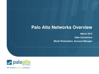
IP IP IP Ethernet interface Message, Segment, Packet, and Frame host host HTTPmessage HTTP HTTP TCP segment TCP TCP router router IP packet IP packet IPpacket IP Ethernet interface SONET interface Ethernet interface Ethernet interface SONET interface Ethernetframe SONET frame 3 Ethernet frame
Topics • Link layer: • Ethernet and CSMA/CD • Wireless protocols and CSMA/CA • Spanning tree, switching and bridging • Translating addrs: DHCP and ARP • Network layer: • IPv4, addressing, and forwarding • IP routing • Link-state and distance vector • BGP: path vector, policies • IP multicast and anycast • Middleboxes: NATs, firewalls • Tunneling: MPLS, IPSec • Addt. Considerations: mobility, DTNs • Transport layer: • Socket interface • UDP • TCP • Reliability • Congestion Control • Reliable multicast • Application layer: • Translating names: DNS • HTTP and CDNs • Overlay networks • Peer-to-peer and DHTs • Email
Link-Layer Services • Encoding • Representing the 0s and 1s • Framing • Encapsulating packet into frame, adding header and trailer • Using MAC addresses, rather than IP addresses • Error detection • Errors caused by signal attenuation, noise. • Receiver detecting presence of errors
Multiple Access Protocol • Single shared broadcast channel • Avoid having multiple nodes speaking at once • Otherwise, collisions lead to garbled data • Multiple access protocol • Distributed algorithm for sharing the channel • Algorithm determines which node can transmit • Classes of techniques • Channel partitioning: divide channel into pieces • Time-division multiplexing, frequency division multiplexing • Taking turns: passing a token for right to transmit • Random access: allow collisions, and then recover
Key Ideas of Random Access • Carrier Sense (CS) • Listen before speaking, and don’t interrupt • Checking if someone else is already sending data • … and waiting till the other node is done • Collision Detection (CD) • If someone else starts talking at the same time, stop • Realizing when two nodes are transmitting at once • …by detecting that the data on the wire is garbled • Randomness • Don’t start talking again right away • Waiting for a random time before trying again
Wireless: Avoidance, Not Detection • Collision detection in wired Ethernet • Station listens while transmitting • Detects collision with other transmission • Aborts transmission and tries sending again • Problem #1: cannot detect all collisions • Hidden terminal problem • Fading • Problem #2: listening while sending • Strength of received signal is much smaller • Expensive to build hardware that detects collisions • So, 802.11 does not do collision detection
Medium Access Control in 802.11 • Collision avoidance, not detection • First exchange control frames before transmitting data • Sender issues “Request to Send” (RTS), including length of data • Receiver responds with “Clear to Send” (CTS) • If sender sees CTS, transmits data (of specified length) • If other node sees CTS, will idle for specified period • If other node sees RTS but not CTS, free to send • Link-layer acknowledgment and retransmission • CRC to detect errors • Receiving station sends an acknowledgment • Sending station retransmits if no ACK is received • Giving up after a few failed transmissions
Scaling the Link Layer • Ethernet traditionally limited by fading signal strength in long wires • Introduction of hubs/repeaters to rebroadcast • Still a maximum “length” for a Ethernet segment • Otherwise, two nodes might be too far for carrier sense to detect concurrent broadcasts • Further, too many nodes in shorter Ethernet can yield low transmissions rates • Constantly conflict with one another
Bridges/Switches: Traffic Isolation • Switch breaks subnet into LAN segments • Switch filters packets • Frame only forwarded to the necessary segments • Segments can support separate transmissions switch/bridge segment hub hub hub segment segment
Self Learning: Building the Table • When a frame arrives • Inspect the source MAC address • Associate the address with the incoming interface • Store the mapping in the switch table • Use a time-to-live field to eventually forget the mapping B A C Switch learns how to reach A D 15
Solution: Spanning Trees • Ensure the topology has no loops • Avoid using some of the links when flooding • … to avoid forming a loop • Spanning tree • Sub-graph that covers all vertices but contains no cycles • Links not in the spanning tree do not forward frames 16
Evolution Toward Virtual LANs • In the olden days… • Thick cables snaked through cable ducts in buildings • Every computer they passed was plugged in • All people in adjacent offices were put on the same LAN • Independent of whether they belonged together or not • More recently… • Hubs and switches changed all that • Every office connected to central wiring closets • Often multiple LANs (k hubs) connected by switches • Flexibility in mapping offices to different LANs Group users based on organizational structure, rather than the physical layout of the building. 17
Example: Two Virtual LANs R R O R R O O O O RO R O R O R O R Red VLAN and Orange VLAN Switches forward traffic as needed
IP Packet Structure 4-bit Header Length 8-bit Type of Service (TOS) 4-bit Version 16-bit Total Length (Bytes) 3-bit Flags 16-bit Identification 13-bit Fragment Offset 8-bit Time to Live (TTL) 8-bit Protocol 16-bit Header Checksum 32-bit Source IP Address 32-bit Destination IP Address Options (if any) Payload
Source Address: What if Source Lies? • Source address should be the sending host • But, who’s checking, anyway? • You could send packets with any source you want • Why would someone want to do this? • Launch a denial-of-service attack • Send excessive packets to the destination • … to overload the node, or the links leading to node • Evade detection by “spoofing” • But, the victim could identify you by the source address • So, you can put someone else’s source address in packets • Also, an attack against the spoofed host • Spoofed host is wrongly blamed • Spoofed host may receive return traffic from receiver
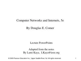
00001100 00100010 10011110 00000101 Hierarchical Addressing: IP Prefixes 12 34 158 5 Network (24 bits) Host (8 bits) • IP addresses can be divided into two portions • Network (left) and host (right) • 12.34.158.0/24 is a 24-bit prefix • Which covers 28 addresses (e.g., up to 255 hosts)
Classful Addressing • In the olden days, only fixed allocation sizes • Class A: 0* • Very large /8 blocks (e.g., MIT has 18.0.0.0/8) • Class B: 10* • Large /16 blocks (e.g,. Princeton has 128.112.0.0/16) • Class C: 110* • Small /24 blocks (e.g., AT&T Labs has 192.20.225.0/24) • Class D: 1110* • Multicast groups • Class E: 11110* • Reserved for future use • This is why folks use dotted-quad notation!
CIDR: Hierarchal Address Allocation • Prefixes are key to Internet scalability • Address allocated in contiguous chunks (prefixes) • Routing protocols and packet forwarding based on prefixes • Today, routing tables contain ~200,000 prefixes (vs. 4B) 12.0.0.0/16 : : : 12.1.0.0/16 12.3.0.0/24 12.2.0.0/16 12.3.1.0/24 : : 12.3.0.0/16 : : : 12.0.0.0/8 12.3.254.0/24 12.253.0.0/19 12.253.32.0/19 12.253.64.0/19 12.253.96.0/19 12.254.0.0/16 12.253.128.0/19 12.253.160.0/19
Two types of addresses Provider independent (from IANA) Provider allocated (from upstream ISP) Provider allocated addresses seem to offer more potential for aggregation (and reducing routing table size), but not always so…
Scalability: Address Aggregation Provider is given 201.10.0.0/21 Provider 201.10.0.0/22 201.10.4.0/24 201.10.5.0/24 201.10.6.0/23 Routers in rest of Internet just need to know how to reach 201.10.0.0/21. Provider can direct IP packets to appropriate customer.
But, Aggregation Not Always Possible 201.10.0.0/21 Provider 1 Provider 2 201.10.6.0/23 201.10.0.0/22 201.10.4.0/24 201.10.5.0/24 Multi-homedcustomer (201.10.6.0/23) has two providers. Other parts of the Internet need to know how to reach these destinations through both providers.
CIDR Makes Packet Forwarding Harder 201.10.0.0/21 Provider 1 Provider 2 • Forwarding table may have many matches • E.g., entries for 201.10.0.0/21 and 201.10.6.0/23 • The IP address 201.10.6.17 would match both! • Use Longest Prefix Matching • Can lead to routing table expansion • To satify LPM, need to announce /23 from both 1 and 2 201.10.6.0/23 201.10.0.0/22 201.10.4.0/24 201.10.5.0/24
Two types of addresses • Provider independent (from IANA) • Provider allocated (from upstream ISP) • Provider allocated addresses seem to offer more potential for aggregation (and reducing routing table size), but not always so… • Multi-homing a PA address • Traffic engineering between multiple links to same single provider
Internet-wide Internet Routing 4 3 5 2 6 7 1 Web server Client • AS-level topology • Destinations are IP prefixes (e.g., 12.0.0.0/8) • Nodes are Autonomous Systems (ASes) • Edges are links and business relationships
Intradomain routing(Interior Gateway Protocol – IGP) Link-state: • Keep complete map of all links • Fast convergence • Node can advertise incorrect link cost • Each node computes only its own table • OSPF, IS-IS, … Distance Vector: • Keep only next-hop and cost information for each destination • Convergence time varies (can be loops, count-to-infinity) • DV node can advertise incorrect path cost • Each node’s table used by others (error propagates) • RIP, …
2 Path-Vector Routing “d: path (2,1)” “d: path (1)” 3 1 data traffic data traffic d • Extension of distance-vector routing • Support flexible routing policies • Avoid count-to-infinity problem • Key idea: advertise the entire path • Distance vector: send distance metric per dest d • Path vector: send the entire path for each dest d
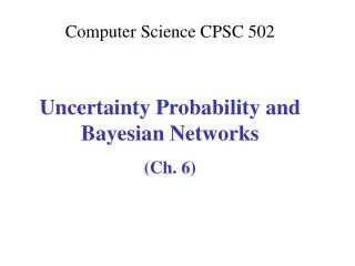
BGP Route 12.127.0.121 192.0.2.1 AS 7018 AT&T AS 88 AS 11 Yale Princeton 128.112.0.0/16 AS path = 88 Next Hop = 192.0.2.1 128.112.0.0/16 AS path = 7018 88 Next Hop = 12.127.0.121 • Destination prefix (e.g., 128.112.0.0/16) • Route attributes, including • AS path (e.g., “7018 88”) • Next-hop IP address (e.g., 12.127.0.121)
BGP Policy: Applying Policy to Routes • Import policy • Filter unwanted routes from neighbor • E.g. prefix that your customer doesn’t own • Manipulate attributes to influence path selection • E.g., assign local preference to favored routes • Export policy • Filter routes you don’t want to tell your neighbor • E.g., don’t tell a peer a route learned from other peer • Manipulate attributes to control what they see • E.g., make a path look artificially longer than it is
announcements traffic Customer-Provider Relationship Traffic to the customer Traffic from the customer d provider provider customer d customer • Customer needs to be reachable from everyone • Provider tells all neighbors how to reach the customer • Customer does not want to provide transit service • Customer does not let its providers route through it
announcements traffic Peer-Peer Relationship Traffic to/from the peer and its customers peer peer d • Peers exchange traffic between customers • AS exports only customer routes to a peer • AS exports a peer’s routes only to its customers • Often the relationship is settlement-free (i.e., no $$$)
Identify the peer/transit links! 4 3 5 2 6 7 1 Web server Client
Extending the network layer Anycast Multicast Middleboxes
Motivation for IP anycast • Failure problem: client has resolved IP address • What if IP address can represent many servers? • Load-balancing/failover via IP addr, rather than DNS • IP anycast is simple reuse of existing protocols • Multiple instances of a service share same IP address • Each instance announces IP address / prefix in BGP / IGP • Routing infrastructure directs packets to nearest instance of the service • Can use same selection criteria as installing routes in the FIB • No special capabilities in servers, clients, or network
Downsides of IP anycast • Many Tier-1 ISPs ingress filter prefixes > /24 • Publish a /24 to get a “single” anycasted address: Poor utilization • Scales poorly with the # anycast groups • Each group needs entry in global routing table • Not trivial to deploy • Obtain an IP prefix and AS number; speak BGP • Subject to the limitations of IP routing • No notion of load or other application-layer metrics • Convergence time can be slow (as BGP or IGP convergence) • Failover doesn’t really work with TCP • TCP is stateful; other server instances will just respond with RSTs • Anycast may react to network changes, even though server online • Root name servers (UDP) are anycasted, little else
IP Multicast • Simple to use in applications • Multicast “group” defined by IP multicast address • IP multicast addresses look similar to IP unicast addrs • 224.0.0.0 to 239.255.255.255 (RPC 3171) • Best effort delivery only • Sender issues single datagram to IP multicast address • Routers delivery packets to all subnetworks that have a receiver “belonging” to the group • Receiver-driven membership • Receivers join groups by informing upstream routers • Internet Group Management Protocol (v3: RFC 3376)
Middleboxes • Middleboxes are intermediaries • Interposed in-between the communicating hosts • Often without knowledge of one or both parties • Examples • Network address translators • Firewalls • Traffic shapers • Intrusion detection systems • Transparent Web proxy caches • Application accelerators
Two Views of Middleboxes • An abomination • Violation of layering • Cause confusion in reasoning about the network • Responsible for many subtle bugs • A practical necessity • Solving real and pressing problems • Needs that are not likely to go away • Would they arise in any edge-empowered network, even if redesigned from scratch?
Port-Translating NAT • Map outgoing packets • Replace source address with NAT address • Replace source port number with a new port number • Remote hosts respond using (NAT address, new port #) • Maintain a translation table • Store map of (src addr, port #) to (NAT addr, new port #) • Map incoming packets • Consult the translation table • Map the destination address and port number • Local host receives the incoming packet
Two Basic Transport Features Server host 128.2.194.242 Service request for 128.2.194.242:80 (i.e., the Web server) Client host Web server (port 80) OS Client Echo server (port 7) IP payload Demultiplexing: port numbers Error detection: checksums detect corruption
User Datagram Protocol (UDP) SRC port DST port checksum length DATA • Datagram messaging service • Demultiplexing of messages: port numbers • Detecting corrupted messages: checksum • Lightweight communication between processes • Send messages to and receive them from a socket • Avoid overhead and delays of ordered, reliable delivery
Transmission Control Protocol (TCP) • Stream-of-bytes service • Sends and receives a stream of bytes, not messages • Reliable, in-order delivery • Checksums to detect corrupted data • Sequence numbers to detect losses and reorder data • Acknowledgments & retransmissions for reliable delivery • Connection oriented • Explicit set-up and tear-down of TCP session • Flow control • Prevent overflow of the receiver’s buffer space • Congestion control • Adapt to network congestion for the greater good
Establishing a TCP Connection B A SYN Each host tells its ISN to the other host. SYN ACK ACK Data Data • Three-way handshake to establish connection • Host A sends a SYNchronize(open) to the host B • Host B returns a SYN ACKnowledgment (SYN ACK) • Host A sends anACK to acknowledge the SYN ACK
TCP “Stream of Bytes” Service Host A Byte 0 Byte 1 Byte 2 Byte 3 Byte 80 Host B Byte 0 Byte 1 Byte 2 Byte 3 Byte 80