Building a Truss Bridge Model: Engineering Overview
Learn about truss bridges, components, types, structural concepts, steel construction, connections, foundations, and types of truss bridges through this hands-on activity. Understand the forces and dynamics involved in supporting structures.

Building a Truss Bridge Model: Engineering Overview
E N D
Presentation Transcript
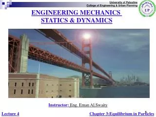
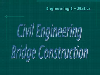
Engineering I – Statics Civil Engineering Bridge Construction
Building a Model of a Truss Bridge • Overview: • Design is the essence of all engineering. However, in this activity you will be building a bridge that has already been designed by someone else. By doing so you will learn the essential elements needed in designing a structure.
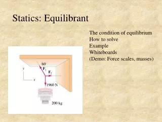
Building a Model of a Truss Bridge • Specific Outcomes: • Explain what a truss is. • Identify the major components of a truss bridge. • Identify the types of truss bridges. • Explain the following fundamental structural engineering concepts: force, load, reaction, equilibrium, tension, compression, and strength.
Building a Model of a Truss Bridge • 1. Component Parts of a Truss Bridge • What is a Truss? • A truss is a structure composed of members connected together to form a rigid framework. • Members are the load-carrying components of a structure. In most trusses, members are arranged in interconnected triangles, as shown below. • Because of this configuration, truss members carry load primarily in tension and compression. (We’ll discuss these terms in Section 3 below.) • Because trusses are very strong for their weight, they are often used to span long distances. • Truss bridges have become somewhat less common in recent years. Today trusses are often used in the roofs of buildings and stadiums, in towers, construction cranes, and many similar structures and Machines.
Building a Model of a Truss Bridge • The three-dimensional bridge structure has two main load-carrying trusses. Each truss is composed of a top chord, a bottom chord, and several verticals and diagonals. The two trusses are connected together by a series of transverse members—struts, lateral bracing, and floor beams.
Building a Model of a Truss Bridge • Modern Truss bridges are made of steel. • The steel is molded into many shapes and sizes. • Examples are hollow tubes and solid bars • The deck of a modern truss bridge is commonly constructed of concrete. • Material strength varies.
Building a Model of a Truss Bridge • Structural members are connected by connections. These connections are essential in the ability o the structure in carrying a load. • Two common types: • Pinned Connections-uses a single pin to connect two or more pieces together. • Gusset plate connections-joined together by one or two heavy metal gusset plates, which are attached to the individual members with rivets, bolts and welds. Gusset Plate Connections are more common today.
Building a Model of a Truss Bridge • Foundations • Every structure must be supported on a firm foundation, which distributes the weight of the structure to the soil or rock below it. Bridges use two different types of foundations. • The ends of a bridge usually rest on abutments, which serve two functions simultaneously—they support the bridge and also hold back the soil that is filled in behind them. • If the bridge requires additional support in the middle of the gap, one or more piers are used, as shown below. • Abutments and piers are normally made of concrete. • All structural foundations are designed by civil engineers with special expertise in soils and foundations. These men and women are called geotechnical engineers.
Building a Model of a Truss Bridge • Types of Truss Bridges • Truss bridges are grouped into three general categories, based on their deck location. • If the deck is located at the level of the bottom chord, the bridge is called a through truss. • A pony truss looks just like a through truss, except it is not as high and has no lateral bracing between the top chords. • If the deck is located at the level of the top chord, the bridge is called a deck truss. • Trusses are also classified according to the geometric arrangement of their chords, verticals, and diagonals. The diagrams on page 1-6 show 15 of the most common truss configurations, many of which were named for the 19th century engineers who developed them.
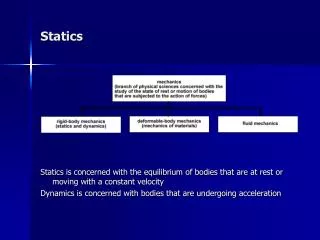
Building a Model of a Truss Bridge • How a structure carries a load. • Mechanical Engineering has two major disciplines: • Statics • Dynamics • Statics refers to all the forces acting upon bodies at rest. • Dynamics refers to all forced acting on bodies in motion. • Much of structural engineering deals with the concept of force. A force is simply a push or a pull applied to an object. • F=ma (Scalar quantity vs. Vector) Force is Vector Quantity. • A force ALWAYS has magnitude and direction. • Example of a truck crossing a bridge. What is the magnitude? In what direction is the force. • Mathematically represented by VECTORS!
10 Newtons Building a Model of a Truss Bridge • Review • Vector is a quantity that has both magnitude and direction. • In structural engineering it is useful to distinguish between three different kinds of forces – • LOADS, REACTIONS, and INTERNAL MEMBER FORCES.
Building a Model of a Truss Bridge • Loads • A force applied to a structure. • Actual bridges are subjected to many different kinds of loads including the following: • Weight of the vehicles and pedestrians crossing the bridge • Weight of the bridge itself • Weight of the asphalt or concrete road surface • Wind pushing sideways on the structure • Weight of snow, ice, or rainwater • Forces caused by earthquakes
Building a Model of a Truss Bridge • Reactions • Newton’s First Law—one of the basic principles of physics—states that an object at rest will remain at rest, provided it is not subjected to an unbalanced force. • Robert Hooke, used Newton’s theory to say: “If a material or a structure is to resist a load, it can only do so by pushing back at it with an equal and opposite force.” • If any structural system is to do its job, then it must somehow manage to produce a push or a pull which is exactly equal & opposite to the force which is being applied to it creating equilibrium. • In other words, if an object is not moving, then the total force acting on it must be zero. When you apply a downward force to the scissors truss, it does not move; thus, according to Newton’s First Law, the total force on the truss must be zero. But how can that be?
Building a Model of a Truss Bridge • Suppose you push down on the nutcracker with a force of 10 newtons. The nutcracker does not move, because the table pushes back upward with a force of 10 newtons. In this particular example, because the structure touches the table at two points, the table actually pushes upward with two forces, each with a magnitude of 5 newtons, as shown below. The structure is said to be in equilibrium, because the total upward force equals the total downward force. • A structure that is not moving must be in equilibrium. • Mathematically, the vector sum of all forces acting on the structure is zero. If we assume that the upward direction is positive, then + 5 + 5 – 10 = 0.
AutoDesk Inventor • Assignment: Draw a simple truss. Place 100lb of force on a top and animate the simulation.
Building a Model of a Truss Bridge • Consider for a moment the simplest form of structure… a branch on a tree. • Suppose we hang a weight, such as an ordinary brick, from some support - the branch - by means of a string. • The weight of the brick, like the weight of Newton’s Apple, is due to WHAT? • Gravity: 9.8 m/sec • Gravity acts on the mass of the brick pulling it downward. • If the brick is not to fall, then it must be sustained in its position in mid-air by a continuing equal and opposite upwards force or pull in the string. • A weak string will break because WHY? • It is Not producing an upward force equal to the weight of the brick, or the force of gravity pulling down on the bricks mass. • The string breaks and the brick will fall to the ground - again, like Newton’s apple.
Building a Model of a Truss Bridge • In our example, the two upward forces are called reactions. • Reactions are forces developed at the supports of a structure, to keep the structure in equilibrium. • Supports are the points where the structure is physically in contact with its surroundings. • On our nutcracker truss, the supports are located at the ends of the handles, where the nutcracker touches the table. On an actual bridge, the supports are located at the abutments or piers. • Geotechnical engineers are particularly interested in the reactions of a structure, because the foundations must be designed to carry these forces safely and efficiently.
Building a Model of a Truss Bridge • Internal Member Forces • When you apply external loads to a structure, external reactions occur at the supports. • But internal forces are also developed within each structural member. In a truss, these internal member forces will always be either tension or compression. • A member in tension is being stretched, like the rubber band in the picture on page 1-8. • Tension is an internal force that tends to make a member longer.
Westpoint Bridge Builder • Use WestPoint Bridge Builder to design the following: • Pratt Truss • K Truss • Pennsylvania • All are 24 meters high with no center pier.
L= 200 cm l = 1 cm Building a Model of a Truss Bridge • PUSHING & PULLING! • No matter how geometrically complicated or varied a structure may be, all structures are either pulled or pushed by the loads & then they stretch; or are pushed and then they are shortened. • EXPERIMENT 1: GOIN’ FISHIN’ AGAIN! • When a material is pulled it is said to be under tension. The increased length divided by the original length is the strain. • Strain = increase of length/original length or • Strain= l/L=e • 1cm/200cm = .005
Building a Model of a Truss Bridge • Stress = load/area. • Area equals the thickness indicated. • Using your data lets determine our stresses on the strings. • Stress = Load/Area • Stress is usually indicated in the following units: MN/m2 • This is the SI (System International) Unit for Stress. • 1 Mega Newton = 1 million newtons which is almost 100 tons of force.
Building a Model of a Truss Bridge • Thus if a rod or material has an original Length (L) and is caused to stretch by an amount (l) by the action of a force on it, then the strain or proportionate change in the length in the rod or material will be (e). • N.B. (Nota Bene) (Note Well); Engineering strains are very small, and so engineers express strains in percentages, which reduces the opportunities for confusion with excess zeroes and decimal places. • EXPERIMENT 2: STRETCH ARMSTRONG
Building a Model of a Truss Bridge • In this class we will test in Pounds per Square Inch (P.S.I.) • Young’s modulus - or how stiff is this material? • Nowadays when we want to test a material we make a ‘test-piece’ from it. • They are tested for stress and strain in ‘testing machines which simulates intended pushing and pulling on the objects. • When we establish the stress and the strain of the material we can use the information to determine Young’s modulus of ELASTICITY! • WHAT????????????? • Young’s Modulus is also known as the Elasticity Modulus or the STIFFNESS of a material. It is determined by the following formula: Stress/Strain=Elasticity Modulus.
Building a Model of a Truss Bridge • Elasticity is the property of returning to an initial form or state following deformation. • Hence we sometimes refer to rubber bands as elastic bands. • Strength, as determined by stress and strain, is not the only important property required of a structural material. • The lengthening and shortening of its elements must not increase indefinitely and must disappear when the action of the load ends. • BALSA WOOD TEST: Please do not snap the balsa wood in half. You will need this for an experiment. • Slightly bend the piece of wood WITHOUT breaking it. • Release the item on the desk top. Notice it returns to its normal shape. • The Balsa wood has a degree of elasticity. • Stress/Strain. It would be determined in the same manner in which we did the fishing line.
Building a Model of a Truss Bridge • Materials that continue to stretch are called yielding. • Materials that do not stretch or have NO elasticity are said to be brittle. • Neither can be used in structural engineering because they fail to meet the main requirement of structural materials: • The lengthening and shortening of its elements must not increase indefinitely and must disappear when the action of the load ends. • ELASTICITY WORKSHEET • Using the data collected on stress and strain, students will determine the elasticity of the fishing line. • On the work sheet provided, fill in the variables and you should be able to determine Young’s modulus (E=Elasticity Modulus) for mono-filament.
Building a Model of a Truss Bridge • Compression: • The force that tries to squeeze or push a material together. • It is the opposite of tension. Tension is the force that pulls forces apart. • BALSA WOOD EXPERIEMENT #2: Take the 4” piece of balsa wood and try and bend it. What do you notice? The Balsa wood is the same material as the larger piece. • Why isn’t the smaller Balsa wood bending as much as the larger piece? Don’t they come from the same part? • Do both pieces have the same elasticity? • What holds the balsa wood together? • Molecular structure. • Is the big piece of balsa wood the same molecular structure as the smaller one? • YES! • Therefore why does one bend more than the other?
Building a Model of a Truss Bridge • IT DOESN’T!! • The elasticity, the stress, the tension, the compression are all the same in a 1” length or a 1 foot length. • What we see is a small section of the arc or bend. _________________
Building a Model of a Truss Bridge • Strength • What caused the fishing line to break in your first experiment? • The string breaks when its internal member force becomes larger than its strength. • This observation leads us to two closely related definitions: • (1) The strength of a structural component is the largest internal force the component can experience • before it fails. • (2) Failure occurs when the internal force in a structural component becomes larger than its strength.
Building a Model of a Truss Bridge • How does a structure carry a load? Having discussed loads, reactions, internal member forces, and strength,we can now answer the important question posed at the beginning of this section: what does it mean for a structure to carry load? In the next learning activity, you will build and load-test a model bridge. If you build the bridge well, it will carry the load successfully, and you will have an opportunity to observe how the structure works.
Cantilever on Inventor • Design a 1 meter by 2 meter x 20 meter cantilever on Inventor. Apply 100000N of force and fix constrain the opposing end. Animate the stress analysis and look at the amount of deflection. • Deflection Worksheet • Deflection Excel Spreadsheet
Building a Model of a Truss Bridge • FORE! • Cantilever construction systems.