Download

1 / 13
130 likes | 311 Vues
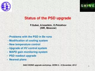
PSD upgrade: concept and plans. F.Guber (INR, Moscow). - Why the PSD upgrade is necessary? - Concept of the PSD temperature stabilization and control - Upgrade of HV control system - Concept of the PSD analog part upgrade - PSD upgrade schedule.

E N D
PSD upgrade: concept and plans F.Guber(INR, Moscow) - Why the PSD upgrade is necessary? - Concept of the PSD temperature stabilization and control - Upgrade of HV control system - Concept of the PSD analog part upgrade - PSD upgrade schedule NA61/SHINE Collaboration meeting, Belgrade, May 27-31, 2013
Why the PSD upgrade is necessary? • 1. The temperature stabilization and temperature control system of MAPDs is • not working properly. • 2. Existing HV control system sets the MAPD voltages but does not readout • HV. During the PSD operation there is no information about real HV at • MAPDs. • 3. There is no monitoring system for the MAPD gains. • 4. The PSD trigger signal is rather slow • problem with the time-amplitude walk and signal delay in trigger box. • 5. Electronics noises are rather small but comparable with MIPs signal. • It makes problem with muon calibration. Quite desirable to reduce the • noise. Upgrade of all items, excluding 4 and 5, doesn’t depend on the choice of PSD readout - DRS4, …., and can be done even if the old PSD readout electronics would be used in 2014 run
Different scenarios for PSD upgrade The PSD (as well as TOF) readout is completely new (DRS4): The PSD upgrade in this case: - temperature stabilization, - MAPD temperature control, - MAPD gain monitoring, - new HV control system, - new amplifiers and trigger can b) The PSD readout is old: The PSD upgrade in this case: - temperature stabilization, - MAPD temperature control, - MAPD gain monitoring, - new HV control system. Trigger signal and readout part can not be upgraded !
Temperature dependence of 7Be peak position Energy in PSD, Ebeam=30AGeV 25.01 – 26.01 27.01 – 28.01 29.01 - 04.02 Energy in PSD, Ebeam=13AGeV Temperature Position of Be peak for for small (left) and 2 large modules (middle and right) using muon calibration parameters. New method of the PSD calibration has been developed by selecting single spectator energy cluster from interaction trigger (see M.Golubeva presentation)
60 layers Al plate HV distributor PCB board End cover Plastic tube Lead-scinti, WLS-fibers with 11 optcal 11 SiMs board with with electronics with air inlet f rom air ~120 cm connectors T sensor (Power 50-100 mWt) distributor box New structure of the PSD electronics and temperature control system 100 – 160 mm Could be ajust in this range MAPDs gain monitoring system Temperature in this area should be 25◦±1◦ CERN cooling team Olivier Crespo-Lopez et al. T sensor Heater (t~25○) Air distributorbox Valve on each module air tube Pumped air
New HV distribution system • Originally developed for COMPAS ECAL modules with 9 MAPDs/module • Can be easy adopted to 10 MAPDs/PSD module. • Permanent check of correct HV values within given HV gate! • Compact design. • Extremely low power consumption. • HV stability – 0.01%. • One external power supply ~12 V. • Slow control exists! • Already tested for a few years! Production by HV systems, Dubna http://hvsys.dubna.ru There is feedback to HV values!
New Slow control system. • Originally developed for COMPAS ECAL • Can control up to 127 devices (modules). • Can control the gain monitoring system too (next slide). • Connection with external computer: USB-2.0 or RS-232. • Internal bus: RS485 • Maximum length of bus cables: 50 m Controller for SC
MAPDs gain monitoring system Control of MAPD gain at ~1% level Gain monitoring system is based on • Stabilized light pulses of LED • is provided by PIN-diode inside with very low temperature dependence. • Controlled by SC (the same as HV) 1 device in one module.
300 ns 60 ns The PSD trigger signal MAPD signal M~5x10⁴ ADC signal integrated signal M~107 At present:the PSD trigger signal comes after integrators with rise time ~60 ns: rather slow and large time-amplitude walk. Needs careful adjustment for each beam energy and each beam ion. Plans: trigger signal after MAPD amplifier – fast signal, no problem with time walk and delay. To have fast trigger new amplifiers and new adders are needed. This action requires the replacement of present FEE by new readout electronics – DRS4, TRB3,….
New fast amplifiers. • New development is needed. • The technical parameters are fixed for a while: • Gain~ 100-120 • Bandwidth ~20 MHz • Dynamical range 1 mV-2.5V • One analog adder in each module for PSD trigger. • Needs additional inputs: connectors, types of cables… • (depends on used readout system –DRS4, TRB3?? • Technical details will be agreed at first half of June.
Start of the PSD electronics upgrade The PSD during Be runs The PSD after April 2013
The PSD electronics upgrade schedule: • 14 -25 April (CERN) • Dismount of existing PSD electronics and MAPDs, preparations to • MAPDs mounting on the same plate in each module - done • - May-June (Moscow) • Preparation the technical task for production of the PSD FEE, HV and • SC systems - in progress • July – September (Moscow) • Production of FEE prototype and test at test-bench. • October-November • Assembling and test of new electronics for one module at CERN • November – February 2014 • Mass production of new PSD electronics. • March – April 2014 • Installation and test of the PSD electronics • and temperature control system at NA61.