Download
1 / 25
250 likes | 422 Vues
ILC Damping Rings: Configuration Status and R&D Plans. Andy Wolski Lawrence Berkeley National Laboratory January 19, 2006. Baseline Configuration. Top Priority: Baseline lattice design by end of March 2006. There are additional specifications on tunes and optics….

E N D
ILC Damping Rings: Configuration Status and R&D Plans Andy Wolski Lawrence Berkeley National Laboratory January 19, 2006
Top Priority: Baseline lattice design by end of March 2006 There are additional specifications on tunes and optics…
Baseline lattice specification allows flexibility in fill patterns
Alternative lattice specification also allows flexibility in fill patterns
ILC Damping Rings R&D Tasks List is in development • 1. Parameter specifications and system interfaces • 1.1 Injected beams • 1.2 Extracted beams • 1.3 Fill patterns and timing issues • 2. Beam dynamics • 2.1 Single-particle dynamics • 2.2 Multi-particle dynamics • 3. Technical subsystems • 3.1 Injection/extraction kickers • 3.2 Damping wiggler • 3.3 Main magnets • 3.4 Orbit and coupling correction • 3.5 RF system • 3.6 Vacuum system • 3.7 Fast (bunch-by-bunch) feedback system • 3.8 Instrumentation and diagnostics
ILC Damping Rings R&D Tasks List: Excerpt • 2. Beam dynamics • 2.1 Single-particle dynamics • 2.1.1 Lattice design • 2.1.1.1 Lattice design for 6 km baseline positron damping rings • Produce a lattice design for the 6 km baseline positron damping rings. The lattice should meet the specifications for damping time, equilibrium emittance, acceptance etc. and include all major subsystems, including injection/extraction sections, orbit and coupling correction systems, RF cavities etc. The circumference should be around 6 km, and should allow for a variety of different fill patterns (different numbers of bunches) without changes in circumference or RF frequency. • Priority/Need: High priority. Required for Reference Design Report, and to allow dynamics studies, engineering designs and costing. • Deadline: March 31, 2006 • Experimental facilities: None • Investigators:Louis Emery (ANL), Aimin Xiao (ANL), Yi Peng Sun (IHEP)
Comments on the R&D Tasks List • The intention is to coordinate activities through a working document that lists R&D objectives, and that can be periodically revised and updated. • Short-term and long-term (ongoing) goals are included. • Objectives are ideally stated in terms of deliverables with deadlines. • Objectives should be developed in consultation between the investigators, the DR Area System Leaders. We want to avoid micromanaging the R&D process. • Resources are widely distributed between different laboratories. This approach provides a coherent framework for collaboration. • We are still in the very early stages. We hope that this approach provides sufficient flexibility to respond to changing project needs.
Links • Final version of Damping Rings Configuration Recommendation Summary Report: • http://www.desy.de/~awolski/ILCDR/DRConfigurationStudy.htm • Final draft of Damping Rings Configuration Studies Report (300 pages): • http://www.desy.de/~awolski/ILCDR/DRConfigurationStudy.htm • Present version of Damping Rings R&D Tasks List: • http://www.desy.de/~awolski/ILCDR/ • Present version of Damping Rings Lattice Specifications: • http://www.desy.de/~awolski/ILCDR/
ILC Damping Rings: Fill Patterns and Timing Issues Andy Wolski Lawrence Berkeley National Laboratory January 19, 2006
General comments • We assume that there will be a benefit in being able to vary the bunch charge and fill pattern in the damping rings. • Lower charge benefits single-bunch instabilities (e.g. microwave). • Fewer bunches can allow longer gaps in some schemes, with potential benefits for electron cloud and ion effects: the benefits need to be better understood. • Effects at the IP drive for lower charge (down to 1×10¹⁰ particles per bunch). • Optimization during commissioning and operation will probably be of value. • Designing for flexibility in the number of bunches places strong constraints on the damping rings’ circumference and the lengths of other systems in ILC. • There are many solutions: here, we consider just two possible schemes. • We assume that gaps in the bunch train in the linac are to be avoided. If gaps are acceptable, this opens up further possibilities.
1 1 1 1 1 1 1 1 1 1 1 1 1 1 1 1 1 2 2 2 2 2 2 2 2 2 2 2 2 2 2 2 2 2 3 3 3 3 3 3 3 3 3 3 3 3 3 3 3 3 3 4 4 4 4 4 4 4 4 4 4 4 4 4 4 4 4 4 5 5 5 5 5 5 5 5 5 5 5 5 5 5 5 5 5 Scheme A: “Fixed bunch spacing” (increase no. of bunches by reducing the gaps) • Extraction kicker fires regularly at intervals of Tlinac • Bunches numbered “1” are extracted on first turn; • bunches numbered “2” are extracted on second turn, etc. • We always extract over a fixed number of turns, so linac RF pulse length does not change. • RF buckets corresponding to extracted bunches are filled immediately by bunches arriving at regular intervals of Tlinac bunch separation in linac = Tlinac bunch separation in linac = Tlinac bunch separation in linac = Tlinac
Example A1: A 6476 m damping ring with 500 MHz RF frequency • Numbers in bold face must be integers in a valid solution. • Input values are in red; values in black or blue are calculated from these. • Grey cells indicate an invalid solution.
Example A2: A 6643 m damping ring with 650 MHz RF frequency • Numbers in bold face must be integers in a valid solution. • Input values are in red; values in black or blue are calculated from these.
1 1 1 2 2 2 3 3 3 4 4 4 5 5 5 6 6 6 Scheme B: “Fixed gaps” (increase no. of bunches by reducing the bunch spacing) • Extraction kicker fires regularly at intervals of Tlinac • Bunches numbered “1” are extracted on first turn; • bunches numbered “2” are extracted on second turn, etc. • We always extract over a fixed number of turns, so linac RF pulse length does not change. • RF buckets corresponding to extracted bunches are filled immediately by bunches arriving at regular intervals of Tlinac 1 3 5 2 4 6 1 3 5 bunch separation in linac = Tlinac = 24 ring RF buckets bunch separation in linac = Tlinac = 12 ring RF buckets
Example B: A 16.2 km damping ring with 500 MHz RF frequency • Numbers in bold face must be integers in a valid solution. • Input values are in red; values in black or blue are calculated from these.
Pros and cons… • Scheme A: Fixed bunch spacing • Provides greater flexibility than fixed gaps: more possibilities for numbers of bunches (e.g. 2700, 3240, 3600, 4050 or 5400 in example A1). • Can be applied in both 6 km and 16 km damping rings… • …but gaps vanish for largest number of bunches in 6 km rings. • “Local current” increases as number of bunches decreased (bunch charge increases) – may adversely affect ions or electron cloud effects. • Scheme B: Fixed gaps • Limited flexibility: probably only two options for number of bunches(e.g. 3010 or 6020 bunches in example B). • Realistically requires a 16 km ring. • Fixed gaps means that ion clearing should be as effective at either number of bunches. • Local current remains constant as number of bunches is changed. + + - - - - + +
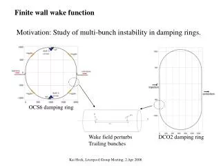
e- damping ring e+ damping rings IP e- source e- linac e- linac e+ linac e+ source L1 L2 L3 L4 Lengths of different sections in ILC cannot be chosen arbitrarily • If L1, L2, L3 and L4 are all integer multiples of the bunch separation in the linacs, then by “time invariance” we see that bunches are always at the right place at the right time. • To retain flexibility in the fill patterns, we need to look for the least common multiple (LLCM) of the various linac bunch separations, Llinac. • L1, L2, L3 and L4 should then all be integer multiples of LLCM.
e- damping ring e+ damping rings IP e- source e- linac e- linac e+ linac e+ source L1 L2 L3 L4 Lengths of sections are determined by linac bunch separation • If L1, L2, L3 and L4 are all integer multiples of the bunch separation in the linacs, then by “time invariance” we see that bunches are always at the right place at the right time. • To retain flexibility in the fill patterns, we need to look for the least common multiple (LLCM) of the various linac bunch separations, Llinac. • L1, L2, L3 and L4 should then all be integer multiples of LLCM. snapshot of bunch positions
e- damping ring e+ damping rings IP e- source e- linac e- linac e+ linac e+ source L1 L2 L3 L4 We can retain flexibility by choosing lengths carefully • In example 1, the bunch separations in the linac are Tlinac = (360, 300, 270, 240, 180) ns. • LCM(360, 300, 270, 240, 180) = 10800, or LLCM = 3237.8 m. This is inconveniently large. • LCM(360, 300, 270, 240, 180) = 2160, or LLCM = 647.55 m. This is better. • LCM(360, 300,270, 240, 180) = 720, or LLCM = 215.85 m. This could be appropriate for the 2nd IP.
L1 L2 L3 L4 Example, using 6476 m damping ring with 500 MHz RF frequency Note: If we do not start e+ DR extraction before there are new e+ bunches arriving at the injection point, then a number of e- bunches at the head of the train have nothing to collide with. We would lose about 10% of the luminosity this way, compared to the case where all bunches collide.
Example, with 2nd IP IP´ L1 L´2 L´3 IP L4
Final Remarks • If the damping ring circumference is chosen carefully, there is significant operational flexibility (up to a factor of two) in the number of bunches in a full ILC bunch train. • There is little benefit in a 650 MHz RF system in the damping ring, compared to a 500 MHz RF system, in terms of the flexibility in fill patterns. • In a ~ 6 km damping ring, operating with ~ 5400 bunches means eliminating any gaps. This could cause problems with ions or electron cloud. The rings can still operate with ~ 4000 bunches, with gaps of 64 ns. • A damping ring circumference of ~ 17 km would allow retention of the gaps with a large number of bunches. • Before a change to the baseline DR configuration is proposed (e.g. from 6 km to 17 km rings) • the impact on the damping rings (ion effects, acceptance etc.) needs to be quantified; • the benefits of lower bunch charge at the IP need to be quantified. • Lengths of other sections in the ILC (linacs, e+ transport lines, distance between IPs) must be chosen carefully if operational flexibility in the numbers of bunches is desired. • There are many solutions. Some example have been shown; there may be better solutions. It is not clear how to approach optimization of the parameters.