Download
1 / 52
520 likes | 713 Vues
Tracker DPG status and plans. Fabrizio Palla INFN Pisa. Outline. Data taking at the TIF Main ingredients and plans Simulation Comparison with data and plans Tracking Status of CMSSW to ORCA comparison Cosmic muons tracking Toward tracking in real conditions Alignment Status and plans

E N D
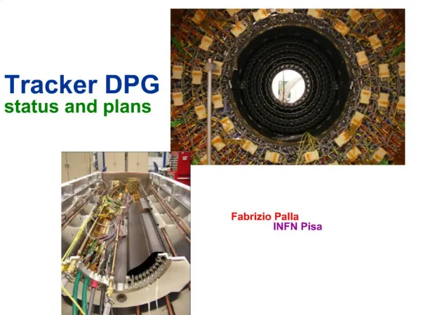
Tracker DPGstatus and plans Fabrizio PallaINFN Pisa
Outline • Data taking at the TIF • Main ingredients and plans • Simulation • Comparison with data and plans • Tracking • Status of CMSSW to ORCA comparison • Cosmic muons tracking • Toward tracking in real conditions • Alignment • Status and plans • Computing • Handling of data at the TAC and distribution to Tiers • N.B. The names in the following slides list only the Italians mainly involved in the items • Apologies for those I will forget !
Data taking at the TIF • TIB inserted into TOB • Ready to take combined (TIB+TOB) data this week (software wise) • Will continue with TEC+ insertion
Third scintillator on left added and connected HV for right PMT was too low and is raised now Will put some lead bricks (10 cm thickness) below Trigger system commissioning
Getting the data out of the Tracker • Used the Si-Tracker in the TIF to commission the Commissioning Software • ~0.5 M channels, ~2K FED channels on each TIB/TID+ and TEC+/- systems • Detector readout was achieved using the "standard" DAQ software, comprising several components related to: • Configuration database, trigger, control and readout. DCS and DSS systems were also in place • The Event Builder used four FilterUnits, so that the large data volumes (>1MB / ev) could be distributed between multiple processing nodes. • Each node processed the data using libraries from the CMSSW framework. DQM: ~4000 histograms/4M bins
Si-strip data taking and DQM • TEC data viewed with DQM • Once cabling information was in place in configuration DB we could run DQM without any problem Summary View Tracker Map S. Dutta, D. Giordano Single Module View
Output root files produced in DQM can be accessed through Web Pure offline usage, no need to run source/collector/client Root files are loaded at start and can be selected from drop-down menu Access files from local area or from castor Requires a dedicated pc @ TAC running http server Offline Web Interface S. Dutta
DQM status and plans • Offline DQM is working, both on TIB/D+ and TOB+ data. • Tests of DQM integration into online to be performed this week • Web interface access outside CERN was successfully tested with Fermilab running DQM at TAC (source/collector/client) • A first prototype of historic DQM shall be delivered soon • Plan to include a set of histograms related to tracks (for each running tracking algorithm) • number of tracks, number of rec hits per track (and vs. phi/eta), chi2, chi2/ndof (vs. eta/phi), pt, px, py, px, eta, phi • Pixel DQM closely follows
Analysis Tools • There exist three complementary analysis methods on reconstructed events: [1] FWLite : acts as a root macro on CMSSW event [2] EDAnalyzer: code is developed in dedicate CMSSW analysis modules. It exploits all CMSSW functionalities. Create histograms [3] EDAnalyzer+root tree: as [2] but dumps all useful info in a root tree, afterwards accessed with a macro • All of these tools are in some way successful: • Developed for MTCC analysis, are widely used • Give feedback on data quality at different levels (e.g. [1] very useful for fast summary plots, [2-3] for more accurate analyses) • Run also on Simulated Data • Note: Analysis tools are not a duplication of DQM; but DQM could profit from experience and development on those tools P. Azzi, D. Giordano, V. Ciulli & al
Visualization • NEW: Iguana Event Display and Tracker Maps are now able to display active modules only • Tracker Map • Readout view is available • further work in progress: TkMap for DQM • The aim for next weeks is to run the event display online during the data tacking Event Display of active TIBD modules - Run 540 RecHits on active TOB modules - Run 2048 M. Mennea, G. Zito
The TAC is a dedicated Tracker Control Room at the TIF To serve the needs of collecting and analysing the data from the 25% Tracker test at the Tracker Integration Facility (TIF) as well as pixels In use since Oct. 1st by DAQ and detector people Computing facilities at TAC G. Bagliesi, T. Boccali, N. De Filippis, S. Sarkar, F. Palla
Computing operations • On-site (TAC) operations • Temporary storage on a PC • Perform o2o • Will convert from StorageManager to EDM-compliant files (now from RU) • Write files to CASTOR once ready • Register files in DBS and DLS • Standard reconstruction run with ProdAgent tool and automatic registration of RECO in DBS/DLS • Off-site operations • Automatic data injection in PhEDEx • Alignment in Tier0 • Re-reconstruction and skimming with Prodagent, if needed, via frontier • End-user analysis via CRAB
Calibration and simulation • Held several “workshops” to tune the simulation with data from Test beams and MTCC • http://indico.cern.ch/conferenceDisplay.py?confId=3896#0 • http://indico.cern.ch/materialDisplay.py?sessionId=4&materialId=0&confId=5422 • http://indico.cern.ch/conferenceDisplay.py?confId=8787 • Some changes done in CMSSW • Saturation of pixels taken into account • E∙B effects in FPIX • Noise vs strip length • Configurable capacitive couplings • Some will come in 1_4_0 • Geometry fixes P. Azzi, F. Ambroglini, L. Fano’, M. Chiorboli
Calibration In RED S/N distribution from tracks, corrected for normal incidence Reco Clusters do not contain gain info. Plot S/N to avoid normalization problems Using the result of this fit and assuming 1 MIP = 312.5 ADC counts ENC=1022 e- 1 MIP = 26.2*3.27*312.5 =26834 e- !! M. Meschini, C. Civinini, G. Lenzi, A. Macchiolo
Material Budget review • 4 teams of people (Pixel, TIB/TID, TEC, TOB) coherently • measure in lab and compare with drawings the dimensions, weights and composition of the volumes implemented in the simulation and change/update accordingly • Have all the software in CMSSW to • Print the characteristic of each Geant volume • Handle mixed materials • Print position and orientation of silicon active areas • A script to run the Geometry Validation Software in one go • automatic check to X/X0 plot and the position/orientation differences with respect to the reference files stored in • /afs/cern.ch/cms/data/CMSSW/Validation/Geometry/reference/Tracker • automatic creation of Material Budget colourful plots (X/X0 vs h) R. Ranieri, G. Sguazzoni, F. Palmonari, A. Rizzi
Tracking progress (I) • Single muon efficiency • About 1% missing for 1 GeV muons P. Azzi, G. Cerati, B. Mangano, S. Magni
Tracking progress (II) • Single pion efficiency • More statistics is available and will be included
Tracking progress (III) • Efficiency in jets • Slighlty smaller efficiency • But proper pT bin not simulated (!) • Missing some MC truth information
Tracking progress (IV) • Fake rate in jets • Same caveats as for “efficiency in jets”
Dead modules in Tracking In realta’ e’ lo 0.3% G. Petrucciani
Track reconstruction in TIF MC Residuals (cm) • Three different algorithms: • cosmic track finder (as in the MTCC) • “standard” CKF • Several fixes to allow non pointing track reconstruction • Road Search TIF Residuals (cm)
Seeds from the 3 outermost TOB layers. (2 RecHits or 3 RecHits) from the TIB layers (it considers also the overlap in z). Soon seeds form TEC modules Efficiency evaluated in Simulated TIF events only for events crossing the TOB and TIB (TEC not considered) Reco: CosmicTrackFinder h f TOB run 2048 • given at least 4 RecHits: • Seed efficiency 99.4% • Track efficiency 98.8% [99.7% given a seed] Tob Residuals • Event Display running in both CMSSW_1_2_X and CMSSW_1_3_0_preX M. Pioppi, D. Benedetti
Reco: Combinatorial Tk Finder • Seeds • TOB only setup • hit pairs on layer 1, 2 and 4, 5,6 • TIB only setup • hit pairs on layer 1, 2 and 3, 4 • TIB+TOB • hit pairs on TIB layer 1,2 and TOB layer 4,5,6 • all packages needed for CTF are planned to enter soon in a prerelease CMSSW_1_3_0_preX • A dedicated package has been created for cosmic seeding • on going studies on data and simulation • Allows reconstruction of multiple tracks in the event TOB run f h G. Lenzi, C. Genta, B. Mangano
Reco: RoadSearch • Road Search Algorithm: • Based on predefined “roads” in the detector • Each road is defined by an inner seed and an outer seed and a collection of silicon modules • Road definition for TOB+ dataset: • Inner Seed: TOB Layer 1+2 • Outer Seed: TOB Layer 5+6 • Running on TOB+ slice test cosmic runs Road Search uses matched hits and stereo+r-phi hits
Alignment exercise at the CSA06 • Read DB object to define the initial misalignment • Run the HIP algorithm on ~1M Z m+ m-AlCaReco datain a parallel way: 20 CPUs on dedicated cmsalca queue (T0) • Output: DB object with new parameters+ convergence plots • Process re-reconstructed data(Z m+ m- reconstructed mass as check) RMS (x,y,z) =(3.8, 30.0, 24.5) mm N. De Filippis, L. Edera TIB DS modules - positions
HIP alignment algorithm: Residuals in the MTCC 2 D. Benedetti, M. Biasini, M. Pioppi, R. Ranieri
Ring 4 Ring 6 Beam- Splitters Laser pulses TEC+ alignment: LAS and cosmics Tracks KF alignment algorithm Preliminary Excellent agreement between LAS and tracks
Surveys and alignment D. Pedrini, M. Rovere, L. Edera, F. Palmonari, R. Covarelli, R. Castello
Lorentz Angle in the MTCC Measure cluster width as a function of the track crossing angle It is minimum for tracks at the drift direction Corrections made for the orientation of the module wrt the B field V. Ciulli, C. Genta, S. Frosali B=0 T B=3.8 T Cluster size Cluster size tan (q) tan (q)
Lorentz angle in Pixel Use fully reconstructed tracks to estimate the angle it makes to the local (x,y) coordinate axes.An independent estimate of the track angle projected into the (x,y) plan can be made by looking at the distribution in (x,y) of the individual pixels within a cluster.If there is no Lorentz shift, these two estimates will be consistent. However, a Lorentz shift will shift the x-coordinate of the hit pixels, and lead to the two results being different. Can measure with ~2% accuracy with 100k muons. (done in MC)
At the TIF (Strips and FW Pixels) and PSI (BPIX) Validate Commissioning code Reconstruction code Noise studies Interference between sub-structures DQM running Cluster reconstruction Calibration Deals with dead channels Deals with merged clusters Thresholds optimization Cosmic Track reconstruction Clusters Gain calibration Geometry and Material budget Alignment LAS vs cosmic tracks Make use of surveys Continue tests on DB access and re-reconstruction At P5 before data comes BPIX commissioning with the rest of Tracker Test/check interference Noise studies Test interference with the rest of CMS. Align with cosmic With (?) and without B field Need triggers from Muons Cosmic track reconstruction Check extrapolation to ECAL, HCAL and Muons relative alignment and synchronization (if B field >0) magnetic field map check Objectives for 2007 – I
Simulation tuning Use TIF and P5 data to tune simulation Detector geometry Material budget Gain simulation Capacitive couplings (when B field in P5) Lorentz angle Check delta rays cut offs Check time resolutions FAMOS Track reconstruction Cosmic muons Beam halo muons V0 and photons Low momentum (below 1 GeV) tracks Nuclear interactions Electron reconstruction Tracking in dense jet environments DAF Pixel tracks Regional reconstruction Partial track reconstruction Code profiling Objectives for 2007 – II
Alignment Data base access of surveys Algorithms HIP and Millipede algorithms ported, KF being ported not yet released Common improvements Use constraint from overlapping sensors Alignment strategies Develop a viable strategy for aligning the full CMS Tracker Before data taking During the 2007 pilot run (only limited part of pixels) 2008 run (full Pixel installed) LAS Compare HW alignment with the cosmics and beam halo muons Vertex reconstruction Beam spot determination Store in DB Study how it could be updated in FU? Measure profile as a function of z Primary vertex determination With and w/o pixels Reconstruction of distant vertices V0 and photon conversions Nuclear interactions Objectives for 2007 – III
Objectives for Alignment • TIF alignment • R. Covarelli and R. Castello • Surveys • F. Palmonari • LAS system fully commissioned • Alignment strategy for full Tracker • M. Rovere, D. Pedrini, L. Edera • Need help in the beam halo, minimum bias, J/Psi
Objectives for Tracking • General CTF maintenance • B. Mangano, G. Cerati, D. Menasce, S. Magni • Cosmic reconstruction • D. Benedetti, C. Genta, G. Lenzi, B. Mangano, M. Pioppi • Tracking with inefficient detectors • G. Petrucciani, F. Ambroglini • V0 and gamma conversions • M. Chiorboli, C. Genta, N. Marinelli • Tracking with displaced beam • G. Petrucciani • Low pT tracks • L. Fano’, F. Ambroglini • Track momentum scale, tracking efficiency • A. Kraan, F. Ligabue, L. Borrello, started, help needed • Efficient Tracking for pions • C. Riccardi, U. Berzano, J. Bernardini, started • Passive Layers and material estimate from data • A. Bocci, R. Ranieri, G. Sguazzoni, started, help needed
Objectives for Simulation • MC tuning vs data • F. Ambroglini, P. Azzi, M. De Mattia • Geometry and Material Budget • F. Palmonari. R. Ranieri, A. Rizzi, G. Sguazzoni, may need some help
Objectives for Data Handling • TIF Data taking and analysis software • V. Ciulli, D. Giordano, S. Dutta, P. Azzi • Commissioning for pixel • V. Chiochia • Unpacking FED • D. Giordano • Gain calibration • D. Giordano, M. Meschini, need help • DQM • S. Dutta, need help • Visualization • M. Mennea, G. Zito
Conclusion and perspectives • Porting of the code from ORCA to CMSSW has been the main activity in 2006 • Mainly finished, continue to port some algorithms • Validation of the PTDR- Vol. 1 plots will be finished by February • Successfully ran on real setups at the MTCC and TIF • This allowed to establish • Commissioning and monitoring the detector • Increasingly good interactions between online, offline, detector and DCS/DSS groups • Data handling and shipment to Tier2 centres for offline analysis • Allows the involve the whole community to analyze Tracker performances • Check geometries and fix bugs • Improve simulation comparing MC to real data • Calibration of the noise, Lorentz angle and gain studies • Reconstruct cosmic muon tracks and start align procedures
Work to do • Year 2007 will continue to test the Tracker and its SW • At the TIF and PSI • On separate setups • On combined and increasingly complex setups • Cosmic ray data taking • At the P5 • As a whole assembled detector and using cosmic rays • Preparation for the 2007 pilot run • Need to increase the track reconstruction capabilities • Recover efficiency for pion tracks, V0, photon conversions, nuclear interactions etc • Need to establish an alignment strategy for startup • Internal Tracker alignment and wrt the outermost CMS systems • Need to establish a strategy for determining • Track efficiency from data • Momentum scale • Material budget • Position error determination
From Channels to Global Coordinates • Need to know a given channel its position in global coordinate system • ~45 k connections between APV pairs and FED input channels • Need to know where APV pairs are placed in space • How is it done? • Detect automatically connections • Performed during commissioning procedures and stored in online DB • Match DCU ID and geometric position done once for all from construction DB and put to online DB • Transfer cabling information to offline DB • Final cabling object in offline DB • Data rearrangement and Online DB to offline DB software developed • Geometry files know where each structure is positioned in space
Local (cluster) reconstruction • Clusterizer module ported to CMSSW since long, however it still miss calibration data for optimal reconstruction in real setups • Pedestals, Noise, bad strips • Computed during commissioning • Transferred to offline DB with scripts. Now are executed “by hand”. Need to make the transfer automatically • Read/write to offline DB very performing (<1 s) using BLOBs • Gain correction • One discrete parameter per APV computed and set in hardware during commissioning runs using tick marks height • … or gain calibration from pixel online • Final correction by using MIPs with data
TK Sectors participating to the Slice Test TOB+ Sector 720 Modules. 28% TOB+ TEC+ Sector 800 Modules. 25 % TEC+ S3 S2 TIB+ Sector and 50% of TID+ (not shown) 640 Modules. 36% TIB/ID+ Service Installation completed for TOB+ Sector, started for TIB/ID+ Sector, to be done for TEC+
QA in the TIF • Tested separately all substructures with excellent results • # Defective channels <0.2% • Reproducible noise behaviour (TIF vs system tests) • TIB/D+ inserted in TOB+ and in TST • TEC+ test finished • TEC- cold test started • TOB/D- cabling finishing in Jan. • FPIX start being shipped to CERN this week. (both 2007 and final, in quarters) • BPIX on test at PSI
Documentation A detailed documentation on procedures for TIF Analysis can be found in the dedicated twiki page https://twiki.cern.ch/twiki/bin/view/CMS/TIFDataAnalysis • The web page contains all the details necessary to run reconstruction algorithms (from FEDBuffers to Tracks), DQM, Event Display and some standard analyses • Using stable code • Dynamic page: new information appears quickly, following the development • last tags to be used • new analysis tool available • Allows feedback from users (very welcome!!!)