Download
1 / 22
230 likes | 367 Vues
Experimental and Numerical investigation of Flow and Heat Transfer in a Ribbed Square Duct. Tony Arts arts@vki.ac.be Carlo Benocci benocci@vki.ac.be Patrick Rambaud rambaud@vki.ac.be. von Karman Institute for Fluid Dynamics. Outline. Motivations & objectives.

E N D
Experimental and Numerical investigation of Flow and Heat Transfer in a Ribbed Square Duct. Tony Arts arts@vki.ac.be Carlo Benocci benocci@vki.ac.be Patrick Rambaud rambaud@vki.ac.be von Karman Institute for Fluid Dynamics
Outline • Motivations & objectives. • Experimental setup and preliminary results (PIV). • Numerical configuration and preliminary results (LES). [1 & 3 ribs] • Comparison & cross validation. • Conclusions & future works
Motivations & Objectives Motivations: • To Improve Turbine Blades Internal Wall Cooling. Why: • Temperature exceeds melting point of blade material (efficient cooling is mandatory to avoid catastrophic failure). How: • Heat transfer inside the blade is enhanced by ribs in cooling channels. Objectives: • Combine experimental & CFD approaches to better understand the physical phenomena. Experiments alone cannot provide all the answers.
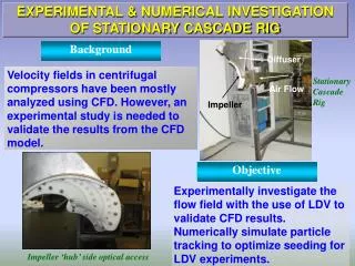
Experimental Setup Scaled-up models (Dh=100mm) of an internal cooling passage for HP turbine. • straight channel • square section, L/Dh=20 • one ribbed wall • square ribs, α=90°, p/h=10, h/Dh=0.3 Seeding distributor Measurement section Measurement performed in between the 4th and the 5th rib
Experimental Techniques Dynamic of the flow: Particle Image Velocimetry • straight channel • square section, L/Dh=20 • one ribbed wall • square ribs, α=90°, p/h=10, h/Dh=0.3 Highly resolved 2D-PIV time averaged data Thermograph of the interface solid/gas: Infrared Camera y z x
Experimental Results Topology of the time averaged flow is guessed (interpretation). This topology will be confirmed but also slightly corrected thanks to CFD.
Possible CFD strategies • Geometries:Engine-like Simplified • Configuration:RotatingNon-Rotating • Heat BC: Temperature/flux at interface wall Conjugate heat transfer • Turbulence: RANS, URANS LES
Coolant Hot gas side heat-flux Simplified method & the conjugate method • CFD done with the commercial code FLUENT [v6.2.16] • Only 1 rib using period boundary conditions • Computation of the temperature field in the fluid and the solid simultaneously • Coupling of heat-transfer through the top surface of the solid part • Applying uniform, constant heat-flux on the bottom of the slab
Dynamic over a single rib LES Good validation of the topology guessed from PIV with some corrections in the wake of the rib. PIV LES
Heat transfer over a single rib Problem in Fluent when using: Periodic condition + Heat transfer + Unsteady solver The temperature is fixed in cell number 1 for several time step (thermal balance). Periodic conditions have to be avoided.
Use of the single rib to generate mean BC • The periodic simulation over 1 rib provides a time averaged inlet BCs. • We will have to face the difficult problem of ‘open’ boundaries in LES => we need to provide a physical turbulent contents. • What about inserting some ribs that will generate the correct turbulent contents => 3 ribs configurations
Computational domain and boundary conditions • A RANS (realizable k-ε) simulation with conjugate heat transfer is done over 3 ribs to have an initial field for the LES. • The full LES simulation over 3 ribs is done. No-diffusion flux outlet bc. • Fluid (air): • ρ = 1.225 kg/m3 • cp= 1006.43 J/kgK • k = 0.0242 W/mK • μ = 1.79×10⁻⁵ Pas • Inlet profiles: • Velocity components from periodic solution + perturbations • Temperature from periodic solution Constant, uniform heat flux: 2220W/m2 • Solid (steel): • ρ = 8030 kg/m3 • cp= 502.48 J/kgK • k = 16.27 W/mK Coupled walls Rest of the walls are considered adiabatic
The mesh Unstructured mesh in the X-Y plane: • Structured blocks at the walls • Refined around the second rib Structured in the Z direction Mesh: 838 028 cells in 120 blocks in the fluiddomain 338 238 cells in 54 blocks in the solid domain 1 176 260 cells in total 1 239 038 nodes
Numerical parameters • Momentum interpolation: Bounded Central Differencing • Pressure interpolation: Standard (second order) • Pressure velocity coupling: SIMPLE • Time discretization:Second order implicit • Turbulence model: Smagorinsky-Lilly with CS = 0.1 • Under-relaxation factors: • Pressure : 0.6 • Momentum : 0.7 • Energy : 1 • Convergence criterion: • 20 iterationsteps • 2×10⁻⁵for the scaled residuals of continuity • Tts-Ro=0= 3×10⁻⁵s = 3.98×10⁻³D/Ub 200s CPU time (no //)
Results of flow-field simulation Contours of mean velocity magnitude with streamlines in the X-Y plane in the symmetry plane of the duct. After only the 3rd rib we start to retrieve the periodic results!! periodic 1st pitch 2nd pitch 3rd pitch
Results of flow-field simulation Profiles of the mean streamwise velocity component Profiles of the mean vertical velocity component
Results of flow-field simulation Profiles of the variance of the streamwise velocity component - <u’u’> Profiles of the covariance of the streamwise and vertical velocity components - <u’v’>
Conclusions about flow-field simulation • The flow is not fully periodic at the second rib • The mean velocity components show a good agreement with the measurements after the 3rd rib • Pressure drop over the 3rd rib matches measurements well • Further extension of the numerical domain is proposed
Heat transfer coefficient: Local Nusselt number: Nusselt number in smooth duct: Enhancement factor: Definitions for heat-flux evaluation Map of temperature field in the symmetry plane from CFD
Results of heat transfer simulation Contours of enhancement factor: “measured” (upper) and LES (lower). Still work to be done one the experimental determination of EF on the Rib! IC + inverse PB LES
Conclusions • Flow-field • Application with LES of the inlet-outlet boundary is successful but the flow gets periodic only after the third rib (bad turbulent contents in the inlet). • The use of extended domain is considered. • Heat transfer • Computation shows good agreement with measurements on the bottom of the channel • Significant differences on the sides of the rib itself (determination of experimental heat flux from solid to air with inverse method has to be improved). Future work • Instantaneous analysis of the CFD fields (how the turbulent structures extract heat from solid). • CFD of different ribs/duct geometries. • Same study in rotating channels.