Download
1 / 39
390 likes | 602 Vues
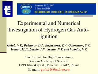
Experimental and Numerical Investigation of Hydrogen Gas Auto-ignition Golub, V.V., Baklanov, D.I., Bazhenova, T.V., Golovastov, S.V., Ivanov, M.F., Laskin, I.N., Semin, N.V. and Volodin, V.V. Joint Institute for High Temperatures, Russian Academy of Sciences

E N D
Experimental and Numerical Investigation of Hydrogen Gas Auto-ignition Golub, V.V., Baklanov, D.I., Bazhenova, T.V., Golovastov, S.V., Ivanov, M.F., Laskin, I.N., Semin, N.V. and Volodin, V.V. Joint Institute for High Temperatures, Russian Academy of Sciences 13/19 Izhorskaya st., Moscow, 125412, Russia E-mail:golub@ihed.ras.ru
Motivation Gas escape from reservoirs and pipelines the ignition of hydrogen
Contents • Introduction • Hydrogen impulse jet self-ignition in semi-confined space • Experimental investigation of impulse jet • Numerical simulation of impulse jet • Numerical simulation of self-ignition • Conclusions • Hydrogen self-ignition in tubes • Experimental investigation of self-ignition in tubes • Numerical simulation of self-ignition in tubes • Conclusions
Contents • Introduction • Hydrogen impulse jet self-ignition in semi-confined space • Experimental investigation of impulse jet • Numerical simulation of impulse jet • Numerical simulation of self-ignition • Conclusions • Hydrogen self-ignition in tubes • Experimental investigation of self-ignition in tubes • Numerical simulation of self-ignition in tubes • Conclusions
Frequency of occurrence of ignition sources (G.R. Astbury, S.J. Hawksworth, 2005).
Condition for ignition of combustible mixture is: The temperature have to be higher than ignition temperature during the time longer than ignition time.
Several ignition mechanisms: • Reverse Joule-Thomson effect • Electrostatic charge generation • Diffusion ignition • Sudden adiabatic compression • Hot surface ignition Astbury G.R., & Hawksworth S.J. (2005).
The phenomenon of diffusion ignition Wolański P., & Wójcicki S. (1973), Investigation into the mechanism of the diffusion ignition of a combustible gas flowing into an oxidizing atmosphere. In Proc. of The 14th Symposium (International) on Combustion (p. 1217)
2005-2007 Astbury G.R., & Hawksworth S.J. (2005). Spontaneous ignition of hydrogen leaks: A review of postulated mechanisms. In Proc. of The International Conference on Hydrogen Safety, Pisa. Bazhenova T.V., Bragin M.V., Golub V.V., Scherbak S.B., & Volodin V.V. (2005). Self ignition of the impulse hydrogen sonic jet emerging in the air semiconfined space. In Abstracts of The 25th International Symposium on Shock Waves, Bangalore (p. 229). Bazhenova T.V., Bragin M.V., Golub V.V., & Ivanov M.F. (2006). Self ignition of a fuel gas upon pulsed efflux into an oxidative medium. Technical Physics Letters, 32(3), 269-271 Liu Y.-F., Tsuboi N., Sato H., Higashino F., Hayashi A.K. (2005). Direct numerical simulation on hydrogen fuel jetting from high pressure tank. In Proc. of The 20th International Colloquium on the Dynamics of Explosions and Reacting Systems, Montreal, Canada. Liu Y.-F., Tsuboi N., Sato H., Higashino F., Hayashi A.K. (2006) Numerical analysis of auto-ignition in high pressure hydrogen jetting into air. In Proc. of The 31st International Symposium on Combustion, Heidelberg, Germany. Mogi T., Shiina H., Kim. D., Horigushi S. (2006). Ignition of high pressure hydrogen by a rapid discharge. In Proc. of The 31st International Symposium on Combustion, Heidelberg, Germany. Dryer F., Chaos M., Zhao Zh., Stein J., Alpert J., & Homer Ch. (2007) Spontaneous ignition of pressurized release of hydrogen and natural gas into air. Combust. Sci. and Tech., 179: 663-694. Golub V.V., Baklanov D.I., Bazhenova T.V., Bragin M.V., Golovastov S.V., Ivanov M.F., & Volodin V.V. (2007) Hydrogen Auto-Ignition During Accidental or Technical Opening of High Pressure TankJournal of Loss Prevention in Process Industries. In print.
Explosive questions: • What is impulse hydrogen jet structure when there is a leak in the tank or during a safety-valve operation? • Can the cold hydrogen jet ignite by itself or not?
Contents • Introduction • Hydrogen impulse jet self-ignition in semi-confined space • Experimental investigation of impulse jet • Numerical simulation of impulse jet • Numerical simulation of self-ignition • Conclusions • Hydrogen self-ignition in tubes • Experimental investigation of self-ignition in tubes • Numerical simulation of self-ignition in tubes • Conclusions
Experimental setup photo 1 – Detonation/shock tube 2 – Receiver/vacuum chamber 3 – IAB-451 schlieren device 4 – High-speed photo-registration camera
Schlieren photographs of the impulse jet In front of the discharging gas the starting shock wave I is propagating, generating the movement of the ambient gas and heating it.
Numerical simulation an impulse jet Density distribution in impulse jet (Ma=1, n=18, t = 50μs) The numerical modeling of flow investigated was carried out by means of Euler equations solution using second order of approximation Steger-Worming scheme. Two components dynamics and mixing were considered.
Density field in the impulse sonic jet The numerical results (right) are compared with the experimental ones(left) (Ma=1, n=18, t = 50μs).
Density of ambient gas – oxygen (top) and discharging gas – hydrogen (bottom) at the time of 1.5 non-dimensional units. The initial conditions are: pressure ratio – 200, temperature ratio – 1, specific heat ratios of both gases – 1.4
Temperature distribution The initial conditions are: pressure ratio – 200,temperature ratio – 1, specific heat ratios of both gases – 1.4
Numerical simulation of hydrogen self-ignition Calculations of the self-ignition of a hydrogen jet were based on a physicochemical model involving the gasdynamic transport of a viscous gas, the kinetics of hydrogen oxidation, the multicomponent diffusion, and heat exchange. The system of equations describing the chemical kinetics included nine equations.
Initial conditions Simulation of mixing and combustion of hydrogen jet, discharging from the reservoir at initial temperature T = 300 K, pressure P = 150-400 bar, hole diameter d = 1-4 mm was considered. Computational grids with a cell size of 0.04-0.1 mm
Temperature distribution along the jet The temperature in the hot zone increases due to generation of heat in the chemical reactions up to 2400 K Stable combustion front is formed at the leading contact surface of the jet even when turbulent mixing mechanisms are not taken into account.
Calculated H2O concentration distribution related to the H2O concentration in fully combusted mixture Z , X– distance from the orifice along and normal to the flow direction. Isolines 1-4 correspond to 70, 30, 10, and 2% respectively.t = 8 μs
Concentrations of species along the jet P0 = 400 atm d = 4 mm t = 8µs Mixing region on contact surface Primary shock Isentropic expansion Mach disk
Maximum temperature-time distributionsDischarging and ambient gas temperatures 300 K, – ignition occurs followed by steady-state – ignition occurs, but extinction is expected – no ignition and no combustion
Conclusions I • The possible reason of combustible gas self-ignition could be the gas ignition on the contact surface separating discharging gas from surrounding oxidizer heater by the primary shock wave. • The self-ignition in the emitted jet takes place if the initial hydrogen pressure in the vessel on the order of 150-400 bar, temperature of hydrogen and surrounding gas (air) 300 K and the hole diameter is more than 3 mm. If, under the same initial temperature and pressure the hole diameter is 2.6 mm or less combustion breaks. • The character of the observed process strongly depends on the initial temperature of hydrogen and air: the emitted jet exhibits self-ignition at an initial pressure of 200 bar and hole diameter 2 mm if the initial temperature of the environment is increased to 400 K.
Contents • Introduction • Hydrogen impulse jet self-ignition in semi-confined space • Experimental investigation of impulse jet • Numerical simulation of impulse jet • Numerical simulation of self-ignition • Conclusions • Hydrogen self-ignition in tubes • Experimental investigation of self-ignition in tubes • Numerical simulation of self-ignition in tubes • Conclusions
Explosive questions: • Is it possible the hydrogen self-ignition in tubes? • Where and when will hydrogen self-ignition occur? • Is there an influence of cross-section shape of tube on self-ignition?
Experimental investigation of self-ignition in tubes Schematic of experimental setups. a) low pressure tube of round cross section; b) low pressure tube of rectangular cross section. 1 – hydrogen bottle, 2 – manometer, 3 – high pressure chamber, 4 – diaphragm block, 5 – copper diaphragm (burst disk), 6 – pressure transducers (PT), 7 – light sensors (LS), 8 – low pressure chamber; 9 – buster chamber. X – distance between diaphragm and pressure transducer.
Low-pressure chamber of cylindrical cross-section Picture of low-pressure chamber of round cross section. 1 – holder for light sensor, 2 – connector of the low-pressure tube with the diaphragm block, 3 – lock-nut with hole diameter of 5 mm, 4 – copper diaphragm of 10 mm in diameter, 5 – diaphragm block, 6 – the low-pressure chamber with connector to buster chamber, 7 – pressure transducer in holder.
Low-pressure chamber of rectangular cross-section Picture of the low-pressure chamber of rectangular cross section (a) and its segments (b). 1 – segments of the low-pressure chamber, 2 – diaphragm block, 3 – connector of the low-pressure tube with the diaphragm block, 4 – copper gasket, 5 – connector of the low-pressure tube with the buster chamber, 6 – holders of light sensor, 7 – pressure transducers in holders.
Pressure (a) and temperature (b) distribution along the tube at moment of time t1.
Self-ignition processes in rectangular tube 34 atm 25 atm X=143mm X=143mm X=93mm X=93mm X=43mm X=43mm 56 atm 40 atm X=143mm X=143mm X=93mm X=93mm X=43mm X=43mm Oscillogramms readings of the pressure and light intensity. Pressure increase leads more close to the burst disk onset of combustion. X – distance between diaphragm and pressure transducer.
Self-ignition length in cylindrical tubes P=46 atm P=94 atm P=52 atm P=96 atm X=90 mm X=33 mm 7 – pressure signal, 8 – light signal.
Numerical simulation of self-ignition of the hydrogen discharge into tube • The boundary conditions: • The dimensions of tube and high-pressure chamber correspond to experimental setup ones. • The initial conditions: • Low-pressure chamber: air (mass fraction of O2 = 0.23, mass fraction of N2 = 0.77), pressure P = 1 atm, temperature T = 300 K. • High-pressure chamber: hydrogen (mass fraction of H2 = 1), pressure P = 20 – 100 atm, temperature T = 300 K.
Calculated distributions of mass fraction of water vapour Before the time moment of 40 μs the water concentration is about zero. After 50 μs the ignition with the subsequent combustion occurs. The water concentration increases to the value of about 0.3.
Calculated x-t diagram of self-ignition development The mixing of hydrogen with air occurs on the contact surface immediately after the burst. Mixture cloud drifts downstream along the tube. At the some moment ignition occurs. Combustion region involves fresh hydrogen and air from both sides of the burning cloud. Combustion, which being started as kinetic one, acquires diffusion character. Heat release and flame turbulence intensify mixing of reagents and such burning cloud may propagate along the tube far enough. Initial pressure of hydrogen – 80 atm.
Correlations between the pressure limit and the length required for self-ignition in cylindrical and rectangular tube Decrease of hydrogen pressure leads to the increase of length required for the self-ignition. In rectangular tube self-ignition occurs at the pressures lower by 1.5-2 times than that in cylindrical tube. Self-ignition limits of hydrogen in the cylindrical (5,6) and rectangular (7) tubes. X – distance from the burst disk along the axis of the tube, P0 – initial pressure in high-pressure chamber. 1 – ignition in the cylindrical tube, experiment; 2 – no ignition in the cylindrical tube, experiment; 3 – ignition in the rectangular tube, experiment; 4 – no ignition in rectangular tube, experiment; 5 – self-ignition limit in the cylindrical tube, experiment; 6 – self-ignition limit in the cylindrical tube, numerical calculation; 7 – self-ignition limit in the rectangular tube, experiment.
Conclusions II • Hydrogen self-ignition in the tubes of round and rectangular cross section is possible at hydrogen initial pressure of 40 atm and higher. • Experimental and numerical work has shown that increases in the initial pressure in the high-pressure chamber decreases the distance from the burst location to the hydrogen ignition point on the contact surface. • It has been shown experimentally and numerically that at the same cross section area the self-ignition in the narrow rectangular tube occurred at lower pressure than that in cylindrical tube. At the initial pressure in high pressure chamber less on 15-20 atm self-ignition occurs at the same distance.
The END. Thank You!