Efficient Ventilation Systems Design Guide for Optimal Performance
270 likes | 368 Vues
This comprehensive guide provides step-by-step instructions for selecting the right thermostat valves, determining flow rates, sizing diameters, and calculating pressure losses for optimal ventilation system efficiency.

Efficient Ventilation Systems Design Guide for Optimal Performance
E N D
Presentation Transcript
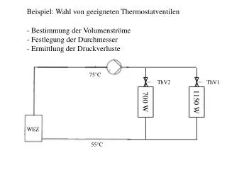
Beispiel: Wahl von geeigneten Thermostatventilen • Bestimmung der Volumenströme • Festlegung der Durchmesser • Ermittlung der Druckverluste 75°C ThV2 ThV1 700 W 1150 W WEZ 55°C
Beispiel: Wahl von geeigneten Thermostatventilen • Bestimmung der Volumenströme • Festlegung der Durchmesser • Ermittlung der Druckverluste 0,051 m³/h 0,082 m³/h 75°C 0,031 m³/h ThV2 ThV1 700 W 1150 W WEZ 55°C
Beispiel: Wahl von geeigneten Thermostatventilen • Bestimmung der Volumenströme • Festlegung der Durchmesser • Ermittlung der Druckverluste alle Rohre DIN EN 10255 - DN10 0,051 m³/h 0,11 m/s 0,082 m³/h 0,18 m/s 75°C 0,031 m³/h 0,07 m/s ThV2 ThV1 700 W 1150 W WEZ 55°C
Ergebnis der Druckverlustberechnung 75°C ??? Pa DIN EN 10255; DN 10 0,082 m³/h 0,18 m/s l = 2,4 m 1 WEZ; 1 Ventil; 10 Bögen 700 W 1150 W WEZ 55°C
Ergebnis der Druckverlustberechnung 75°C 300 Pa • DIN EN 10255; DN 10 • 0,082 m³/h • 0,18 m/s • = 11 • l = 2,4 m 700 W 1150 W WEZ 55°C
Ergebnis der Druckverlustberechnung 0,051 m³/h 0,11 m/s 200 Pa 400 Pa 800 Pa 1600 Pa 300 Pa 75°C 100 Pa • DIN EN 10255; DN 10 • 0,082 m³/h • 0,18 m/s • = 11 • l = 2,4 m ThV1 ThV2 700 W 1150 W 100 Pa 0,031 m³/h 0,07 m/s WEZ 55°C 300 Pa 800 Pa 1600 Pa
Beispielhaftes Ergebnis der Druckverlustberechnung 200 Pa 400 Pa 800 Pa 1600 Pa 300 Pa 75°C 100 Pa ThV1 ThV2 700 W 1150 W 100 Pa WEZ 55°C 300 Pa 800 Pa 1600 Pa
Beispielhaftes Ergebnis der Druckverlustberechnung 200 Pa 400 Pa 800 Pa 1600 Pa 300 Pa 75°C 100 Pa ThV1 ThV2 700 W 1150 W 100 Pa WEZ 55°C 300 Pa 800 Pa 1600 Pa
Beispielhaftes Ergebnis der Druckverlustberechnung • Ventildruckverlust • Wahl der Ventilautorität für THV1 - ungünstigster SK • hier a1 = 0,5 gewählt 75°C ThV2 ThV1 700 W 1150 W WEZ 55°C 3000 Pa ohne THV 6000 Pa
0,1m3/h 0,05m3/h Typ D Typ C
0,05m3/h 0,05m3/h Typ D Typ B
Berechnung Gesamtdruckverlust • Hydraulischer Abgleich durch Druckverlust an THV2 75°C ThV2 ThV1 700 W 1150 W WEZ 55°C 12000 Pa mit THV 12000 Pa
Auslegung 3-WV: b = 11200/600 = 18,7 400 Pa 800 Pa 1600 Pa 300 Pa 75°C 100 Pa ThV1 ThV2 700 W 1150 W 100 Pa WEZ 55°C 300 Pa 800 Pa 1600 Pa 600 Pa 11200 Pa
keine Ventilautorität erforderlich Hoher kvs (niedriges Delta-p) günstig Wahl des Ventils rein nach DN
Auswahl Pumpe: • Vp = 0,082m³/h • Delta-P = 12000 Pa h_P = 12000 Pa/(rho * g) = 1,24 m 200 Pa 400 Pa 800 Pa 1600 Pa 300 Pa 100 Pa 75°C 9000 Pa 6000 Pa 700 W 1150 W 100 Pa WEZ 55°C 300 Pa 800 Pa 1600 Pa