Download
1 / 31
320 likes | 346 Vues
Learn about using OPTO-Isolator in industrial robotics for electrical isolation and protection. Understand wiring, programming, and applications of optocoupling devices.

E N D
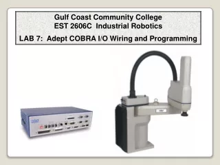
Gulf Coast Community College EST 2606C Industrial Robotics LAB 7: Adept COBRA I/O Wiring and Programming
OPTO-Isolator Before looking at the ADEPT I/O Schematics, let’s look at what an Opto-Isolator is and why it is necessary. The opto-isolator is simply a package that contains both an infrared light-emitting diode (LED) and a photodetector such as a photosensitive transistor . The wave-length responses of the two devices are tailored to be as identical as possible to permit the highest measure of coupling possible. Other circuitry—for example an output amplifier—may be integrated into the package. An opto-isolator is usually thought of as a single integrated package, but opto-isolation can also be achieved by using separate devices.
OPTO-Isolator The device contains an LED and a phototransistor in a light-tight housing to exclude ambient light and without common electrical connection, positioned so that light from the LED will impinge on the photodetector. When an electrical signal is applied to the input of the opto-isolator, its LED lights and illuminates the photodetector, producing a corresponding electrical signal in the output circuit. Schematic diagram of a very simple opto-isolator with an LED and phototransistor. The dashed line represents the isolation barrier, over which there is no electrical contact.
OPTO-Isolator With a photodiode as the detector, the output current is proportional to the intensity of incident light supplied by the emitter. Unlike a transformer the opto-isolator allows DC coupling and can provide any desired degree of electrical isolation and protection from serious overvoltage conditions in one circuit affecting the other. . A simple circuit with an opto-isolator. When switch S1 is closed, LED D1 lights, which triggers phototransistor Q1, which pulls the output pin low. This circuit, thus, acts as a NOT gate.
OPTO-Isolator Applications: Optoisolation of microcontrollers is essential in cases where a microcontroller needs to supply signals to a controller which controls an inductive load such as a motor. Back EMF spikes from an inductive load can easily glitch, or destroy a microcontroller . Back EMF spikes typically manifest themselves as very short duration spikes which may or may not contain enough energy to actually destroy a microcontroller. Nevertheless, these spikes (which can easily approach 100V amplitudes) can easily glitch a microcontroller, even if transient suppression techniques such as generous use of decoupling capacitors, zener diodes etc. are used. Optocoupling should be thought of as absolutely essential if you are using microcontroller boards, and surface mounted boards!
OPTO-Isolator Applications: Among other applications, opto-isolators can help cut down on ground loops, block voltage spikes, and provide electrical isolation. Switched-mode power supplies use optocouplers for mains isolation. As they work in an environment with much electrical noise and with signals which are not small, optocouplers with low transmission ratio are preferred. Where electrical safety is paramount, optocouplers can totally isolate circuitry (which may be touched by humans) from mains electricity. Optocouplers are used to isolate low-current control or signal circuitry from transients generated or transmitted by power supply and high-current control circuits. The latter are used within motor and machine control function blocks.
Connecting Digital I/O to the System: • You can connect digital I/O to the system in several different ways. I/O can be connected in the following configurations: • 1. Connector to rear of the COBRA robot at the XIO connector. • 2. Optional IO Blox connected to the top connector of the COBRA back panel • 3. To the controller using the XDIO connector • To the optional expansion box, the sDIO box • ( more than one can be configured) Adept MV Controller page 91
Digital I/O - XIO Connector The XIO connector on the robot interface panel offers access to digital I/O, 12 inputs and 8 outputs. These signals can be used by V+ to perform various functions in the workcell. • 12 Inputs, signals 1097 to 1108 • 8 Outputs, signals 0097 to 0104
ADEPT IO Blox : The Adept IO Blox device is designed for adding digital input and output capability to Adept products, including the Cobra i-series and s-series robots, Adept Python Linear Modules, Adept Viper robots, and AdeptOne with sEJI robots. The IO Blox offers 8 inputs and 8 outputs, all optically isolated. You can connect up to four IO Blox devices per robot or MB-10 amp. The IO Blox uses clamp-style terminal strips for installing customer wiring. The device can be installed on a robot, or in a panel-mount environment on a DIN Rail. The product is offered with several cable options for different installation locations.
I/O Used on the Gulf Coast Community College ADEPT COBRA Robots
XIO Breakout Cable The XIO Breakout cable is available as an option – see Figure 5-6. This cable connects to the XIO connector on the robot, and provides flying leads on the user’s end, for connecting input and output signals in the workcell. The part number for the cable is 04465-000, and the length is 5 M (16.4 ft). See Table 5-9 on page 64 for the wire chart on the cable. NOTE: this cable is not compatible with the XIO Termination Block.
ADEPT-ONE Robot I/O Testing and Programming
Programming ADEPT I/O Digital I/O Adept controllers can communicate in a digital fashion with external devices using the Digital I/O capability. Digital input reads the status of a signal controlled by user-installed equipment. A typical digital input operation is to wait for a microswitch on a workcell conveyor to close, indicating that an assembly is in the proper place. The WAIT Instruction: The WAIT instruction and SIG function are used to halt program execution until a digital input channel signal achieves a specified state. The program line: WAIT SIG(1001) halts program execution until a switching device attached to digital input channel 1001 is closed
Programming ADEPT I/O SIGNAL Instruction: TheSIGNALinstruction is used for digital output. In the above example, the conveyor belt may need to be stopped after digital input signal 1001 signals that a part is in place. The instruction: SIGNAL(-33) turns off digital output signal 33, causing the conveyor belt connected to signal 33 to stop. When processing on the part is finished and the part needs to be moved out of the work area, the instruction: SIGNAL(33) turns the conveyor belt back on. The digital I/O channels must be installed before they can be accessed by the SIG function or SIGNAL instruction.
Programming ADEPT I/O IF THEN Instruction: If signal 1002 is a sensor indicating a part feeder is empty, the code: IF SIG(1002) THEN ;+ signal received CALL service.feeder() call subroutine program END Soft Signals: Soft signals are used primarily as global flags. The soft signals are in the range 2001 - 2512 and can be used with SIG and SIGNAL. A typical use of soft signals is for intertask communication. Soft signals may be used to communicate between different V+ systems running on multiple system processors.
Gulf Coast Community College EST 2606C Industrial Robotics LAB 7: ADEPT COBRA Robot I/O The Lab Assignments
Lab Procedure: Part 1 – I/O Wiring and testing signals Testing Inputs: Using the Monitor, Test the inputs in the ADEPT COBRA by typing IO on the Monitor screen to display the input signals that are active. Control C lets you exit the program. You should see a screen that looks this with the addresses of the I/O configured for your robot.
2. Block the photo sensor and identify the position for input _______. What is the status ( 1 or 0) of the input? Photo Address _________ Beam blocked ______ Beam not blocked ______ 3. Test the Operator Box by pressing the red button, then the black button, then turn the switch. What address does the screen show for each? Red Button __________ Black Button __________ Switch __________ 4. Test the remaining inputs by placing a temporary jumper from +24vdc at the end of the terminal blocks to the appropriate input terminal in the I/O box. A “1” or a “0” will show on the screen. Inputs 0101, 0102, 0103, 0104, 0105 5. Hold keys Ctrl and C to exit the program and return to the monitor.
6. Test the ADEPT COBRA outputs signals... .DO SIGNAL 0097 Close gripper. .DO SIGNAL - 0097 Open gripper. .DO SIGNAL 0098 Turn on Button box light .DO SIGNAL - 0098 Turn off Button box light .DO SIGNAL 0099 Turn on Relay for the conveyor motor. .DO SIGNAL - 0099 Turn off Relay for the conveyor motor. .DO SIGNAL 0100 Turn on the Parts feeder solenoid. .DO SIGNAL - 0100 Turn off the Parts feeder solenoid.
Lab Procedure: Part 2 – Develop a program to test Signals. Develop a program that sends signals and receive signals using the control button box and the photocell. 1. Type that instruction on screen, “ Please block the photo sensor beam to start the program.” 2. Wait for the photo sensor to be activated (break the beam). It is wired to be active low. So check for a low at Adept signal input 1100. When the beam is broke the program continues. Use the WAIT SIGNAL (-1100) command to wait until for the photo sensor beam is broken. 3. The ADEPT robot will indicate it has received the signal by turning on the light on the control box for 3 seconds,then turn off. Use the delay command for 3 seconds. 4. Type that instruction on screen, “Press the Red Button” 5. Next, press the red button, the robot should type on the screen, “the red button was pressed” Use the WAIT command to wait until for the red button to be pressed. 6. The ADEPT robot will signal it has received the signal by turning on the light on the control box for 3 seconds, then turn off. Use the delay command for 3 seconds. 7. Prompt the operator to press any key on the keyboard to continue along with the message to type instruction on screen, “ Please press the black button” 8. Next, press the black button, the robot should type on the screen, “the black button was pressed” Use the WAIT command to wait until for the black button to be pressed. 9. The ADEPT robot will indicate it has received the signal by turning on the light on the control box for 3 seconds,then turn off. Use the delay command for 3 seconds. 10. Type on the screen,” I/O test completed” Communication should now be operational.
Have Fun, but be careful The End