Download
1 / 7
70 likes | 95 Vues
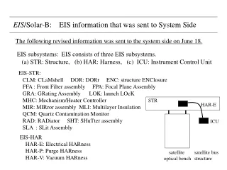
STR. HAR-E. ICU. satellite optical bench. satellite bus structure. EIS /Solar-B: EIS information that was sent to System Side. The following revised information was sent to the system side on June 18. EIS subsystems: EIS consists of three EIS subsystems.

E N D
STR HAR-E ICU satellite optical bench satellite bus structure EIS/Solar-B: EIS information that was sent to System Side The following revised information was sent to the system side on June 18. EIS subsystems: EIS consists of three EIS subsystems. (a) STR: Structure, (b) HAR: Harness, (c) ICU: Instrument Control Unit EIS-STR: CLM: CLaMshell DOR: DORr ENC: structure ENClosure FFA : Front Filter assembly FPA: Focal Plane Assembly GRA: GRating Assembly LOK: launch LOcK MHC: Mechanism/Heater Controller MIR: MIRror assembly MLI: Multilayer Insulation QCM: Quartz Contamination Monitor RAD: RADiator SHT: SHuTter assembly SLA : SLit Assembly EIS-HAR HAR-E: Electrical HARness HAR-P: Purge HARness HAR-V: Vacuum HARness
1 degree EIS-STR EIS/Solar-B: EIS information that was sent to System Side Shape & Size EIS-STR: Rectangular solid Length(z-direction): 3200 mm Height( y-direction): 250 mm Width (x-direction): 550 mm EIS-ICU: Rectangular solid Length: 220 mm (in mounting plane) Width : 150 mm (in mounting plane) Height: 150 mm (normal to mounting plane) Field of View: 1 degree at the edge of EIS aperture. Eigen Frequency: EIS-STR: first resonance frequency 70.4 Hz EIS-ICU: > 100 Hz solar light
EIS/Solar-B: 2. EIS information that was sent to System Side Weight: EIS-STR: 50.3 kg ENC: 25kg, LOK: 1 kg, RAD: 0.3 kg, DOR: 1.4 kg FFA: 0.2 kg CLM(evacuated cavity): 2.5 kg MIR: 5.1 kg (primary mirror: 2.6 kg, mirror mount: 0.5 kg scan mechanism: 2 kg ) SLA: 1.0 kg (slit/slot mechanism: 0.3 kg, focus mechanism: 0.7 kg) SHT: 0.3 kg GRA: 1.6 kg (grating: 0.5 kg, mount: 0.5 kg, focus mechanism: 0.6 kg) FPA: 3.0 kg (camera: 1.0 kg, mount: 0.5 kg, pre-amplifier: 1.5 kg) QCM: 0.4 kg, MHC: 2.5 kg Mounting legs (from system side): 2kg, MLI: 4 kg EIS-HAR: 4 kg EIS-ICU : 6 kg subtotal: 60.3 kg margin : 9 kg total : 69.3 kg
EIS/Solar-B: EIS information that was sent to System Side Property of Moving components component frequency purpose direction angle of motion weight or shift DOR 1 /year protect inside from dirty environment around Y-axis 180 deg /8 sec 0.4 kg CLM once after launch aperture of vacuum enclosure around Y-axis 90 deg 1 kg MIR 1 step/ 2 sec scan for raster observation around Y-axis 1 arcsec / 1 step 3 kg once per 5 min reset scan mirror to start position around Y-axis 8 arcmin / 10 sec 3 kg once per day change of field of view ± X-axis 5 mm / 30 sec 4 kg SHT once per 1 sec adjust exposure duration around Z-axis ~60 deg/0.1 sec 0.2 kg SLA once per an hour change slit/slot around X-axis ~90 deg / 10 sec 0.4 kg once per month ? focus adjustment ± Z-axis ±0.5 mm/ 10 sec 1 kg GRA once per year focus adjustment ± Z-axis ±0.5 mm/ 10 sec 0.8 kg LOK once after launch increase stiffness around X-axis ~30 deg 0.5 kg
EIS/Solar-B: EIS information that was sent to System Side MIR and SHU only move during EIS observations. 0 0.5 2.0 0 5 time (sec) scan scan MIR move move SHU exp. exp. move move move for short exposure exp. exp.
EIS/Solar-B: EIS information that was sent to System Side ・Power consumption: off mode: 0.5 ± 0.5 W standby mode: 15 ± 10 W operational average: 37 ± 7 W operational peak: 55 ± 5 W ・Heater Power: not known because thermal analysis has not been done yet. ・Amount of heat produced: Majority of electric power is dissipated as heat. About 32 W solar light is introduced at the pre-filter location. CCD: 0.6 W, CCD electronics: 8 ± 2 W ・Area attached to satellite: EIS-STR: 48 cm2 in total, EIS-ICU: 5 cm2 in total ・Temperature range: non-operational/transportaion at ground: ‐20-+40 ℃ operatonal: EIS-STR: 20-25 ℃, EIS-ICU: 10-30 ℃ others: : 0-30 ℃ ・Temperature range of actively controlled components: TBD ・Alignment requirement: Angle of optical axes between EIS and others should be within 1 arcmin. ・House keeping telemetry: 1. ICU 28 V voltage and current, 2. two points of ICU temperature 3. seven points of STR temperature, 4. status of DOR(open/close) 5. status of LOK(lock/release), 6. status of FIL(open/close, internal pressure)
EIS/Solar-B: EIS information that was sent to System Side ・Use of pyrotechnic devices: None. ・Necessity of N2 purge during integration and launch preparation. ・Necessity of vacuum pump for FIL evacuation. The pump will be prepared by EIS team. ・TBD side is responsible for harness for purge and vacuum evacuation. ・Thermal property STR: graphite epoxy (black color) α: 0.95, ε: 0.85, TCE = 0.23×10⁻⁶ /K thermal conduction coeff.: TBD, specific heat: TBD ・Radiator Area: 625 cm2 at TBD location, Temperature range: -95 ‐ -65 ℃ ・Temperature range of mechanical interface points: TBD