ATM Switch Design
410 likes | 648 Vues
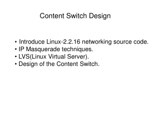
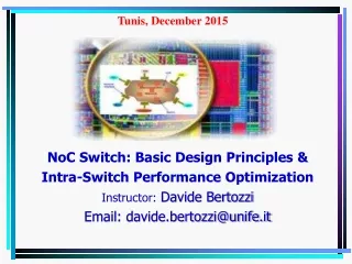
ATM Switch Design. Philip Branch Centre for Telecommunications and Information Engineering (CTIE) Monash University http://www.anspag.monash.edu.au/~pbranch/masters.ppt. ATM Switching Outline. Switching terms and requirements Switch Architectures cross bar, multiple bus, multistage

ATM Switch Design
E N D
Presentation Transcript
ATM Switch Design Philip Branch Centre for Telecommunications and Information Engineering (CTIE) Monash University http://www.anspag.monash.edu.au/~pbranch/masters.ppt
ATM Switching Outline • Switching terms and requirements • Switch Architectures • cross bar, multiple bus, multistage • routing in multistage switches • Buffering schemes in switches • Buffer management • Performance Measures
ATM Switching Terms • Switching • Switching Element • Switching Fabric • Switching System
ATM Switch Requirements • Flexible switching rates • Broadcast and Multicast • Low cell loss probability • Cell Sequence integrity. • High speed switching. • Cell header processing. • VPI/VCI translation
Switch types • Workgroup switches • Campus switches • Core switches
Types of Switching Backplane • Blocking • Routing Conflicts • Cells are lost if no internal buffers. • Cells are stored in a queue if there are internal buffers. • Non-blocking • No internal blocking. • Buffers at the inputs and/or outputs.
ATM Switch Architectures • Crossbar • Most campus switches • Multiple Bus • Most workgroup switches • Multistage • Most core switches
Crossbar • Best performance • Very expensive for large switches • Cost increases as where NXN is the switch size.
Multiple Bus • Lowest cost • Poor scalability • Poor performance due to bus contention Inputs Busses Outputs
Multistage Switches • Interconnection of a number of crossbar switching elements. • Single path or multiple path. • Buffers required to store packets. • Very cost effective. • Highly scalable.
Routing in Multistage Switches • Self routing using destination tags • Internal routing conflicts may • reduce the throughput, • increase the delay and • increase the cell loss in a switch.
Self-Routing Principle • VPI/VCI translation only at the input of the switching network • Cell extended by a switching network internal header • Cell header extension requires increased internal speed. • Suitable for large multistage networks
Tree Saturation • Hot spot traffic • A lot of traffic may be directed to a particular output. • Tree saturation reduces the performance of the switch • Saturated tree blocks traffic to other (non hot) outputs as well.
Batcher-Banyan Switch • A Banyan network has no internal conflict if cells are arranged in ascending or descending order of output destination. • A Batcher network is used to sort cells in ascending order.
Table-controlled VPI/VCI translation • VPI/VCI translation at each switching element. • Cell length need not be altered. • Table contents are updated during connection set-up.
Buffering in Switches • Buffers store the cells that lose routing conflicts. • Location of buffers: • Internally, Externally • Input, Output, Shared, Crosspoint
Input Buffers • Head of line blocking reduces throughput • Inefficient utilisation of buffer space • Simple buffer management
Output Buffers • No head of line blocking • Inefficient utilisation of buffer space • Requires expensive high speed buffers
Shared Buffer • High buffer utilisation. • Needs least amount of buffer space. • Buffer hogging with non uniform traffic. • Complex buffer management strategy. • Needs expensive high speed buffers.
Crosspoint Buffer • Combines the advantages of input and output buffers • Inefficient utilisation of buffer space • Simple buffer management
Buffer Size Requirements • Buffer sizes for average load of 85% at each input and a permissible cell loss probability of 10-9
Buffer Management • Queuing • How to organise buffered cells • Scheduling • When and in what order to service queues
Buffer Management • Which cell to transmit next? • Arbitration strategies based on • Random • fairness • minimise cell loss • minimise cell delay variation
Arbitration Strategies • State dependent: • Longest queue served first • Lengths of buffers have to be compared • Delay dependent: • Queue having the maximum delay served first • Overhead in storing order of arrival information
Buffer Queuing Policies • First in - First out (FIFO) • Strict Priority • Fair Queueing (Per VC queueing) • Weighted Round Robin • Weighted Fair Queuing
Performance Measures • Throughput: Number of cells switched per unit time. • Cell loss probability: Loss from routing conflicts or insufficient capacity • Cell delay: Delay inside switch. • Switching delay: fixed • Queueing delay: variable • jitter: Cell delay variation.
Conclusion • Switching terms and requirements • Switch architectures • Multistage switches • self routing • Batcher-Banyan switch • Buffering schemes • Input, output, shared, crosspoint • Output buffer management • Performance measures
Questions • An ATM switch is functioning normally, until a video server and video client are connected to it. When the video is played back from the server through the switch, other (low bandwidth) applications using the switch fail. The video delivered is jerky. What are some possible explanations for this?