Electrical Schematics and Solderless Breadboards
110 likes | 239 Vues
This guide aims to teach you how to read basic electrical schematics and understand the pin connections on a solderless breadboard. You'll learn how to interpret schematic diagrams, which use standardized symbols to represent electrical components and their interconnections. We also explore the function of solderless breadboards, which are essential for prototyping circuits without soldering. Using an electrical schematic, we'll walk through the process of building various circuits, including an example of a PIC microcontroller circuit with an LED scroller.

Electrical Schematics and Solderless Breadboards
E N D
Presentation Transcript
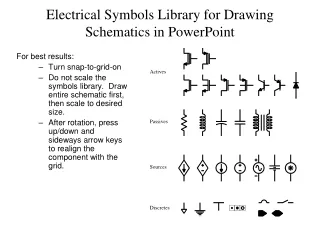
Objectives • Learn how to read a simple electrical schematic. • Understand how the pins on a solderless breadboard are connected. • Use an electrical schematic to build several circuits on a solderless breadboard.
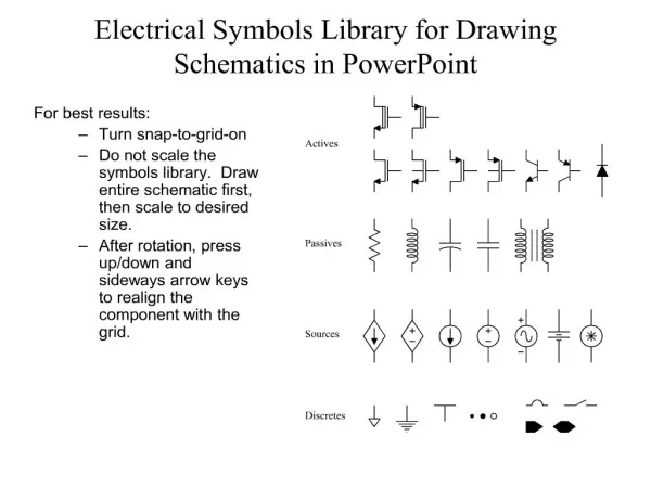
Schematic Diagram: A schematic diagram is a shorthand way to draw an electric circuit. It is a diagram that illustrates components (electrical parts) and how they are connected to each other. Symbols are used to represent circuit components and lines are used to represent wires or connections.
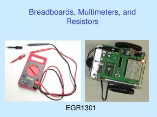
Solderless Breadboards: Solderless breadboards are commonly used in experimentation or to make a prototype of a circuit before the circuit is soldered or made in mass production.