Download
1 / 31
310 likes | 463 Vues
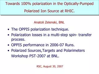
Towards 100% polarization in the Optically-Pumped Polarized Ion Source at RHIC. The OPPIS polarization technique. Polarization losses in a multi-step spin- transfer process. OPPIS performance in 2006-07 Runs. Polarized Sources,Targets and Polarimeters Workshop PST-2007 at BNL.

E N D
Towards 100% polarization in the Optically-Pumped Polarized Ion Source at RHIC. • The OPPIS polarization technique. • Polarization losses in a multi-step spin- transfer process. • OPPIS performance in 2006-07 Runs. • Polarized Sources,Targets and Polarimeters Workshop PST-2007 at BNL. Anatoli Zelenski, BNL RSC, August 30, 2007
Optically-Pumped Polarized H- Ion Source at RHIC. RHIC OPPIS produces reliably 0.5-1.0mA (maximum 1.6 mA) polarized H- ion current. Pulse duration 400 us. Polarization at 200 MeV P = 85-90 %. Beam intensity (ion/pulse) routine operation: Source - 1012 H-/pulse Linac (200MeV) - 5∙1011 Booster - 2∙1011, (50% - scraping). AGS - 1.7∙1011 RHIC - 1.5∙1011 (p/bunch). The RHIC OPPIS was developed in collaboration with TRIUMF and INR, Moscow.
SCHEMATIC LAYOUT OF THE RHIC OPPIS. SCS solenoid Cryopumps SCS -solenoid Rb-cell Pumping laser Probe laser Correction coil 29.2 GHz ECR proton source Na-jet Ionizer cell Sona-shield
Depolarization factors in the OPPIS. P = PRb∙ S ∙ BH2∙ ELS∙ ESona∙ Eion∙ M ~ 85-90% Total: 0.82 - 0.90 (0.9/0.8)4 ~1.6
Polarized beams in RHIC. OPPIS 10∙1011(maximum 40∙1011) polarized H- /pulse, P =85% LINAC 5∙1011 polarized H- /pulse at 200 MeV, P=85% Booster 2∙1011 polarized protons /pulse at 2.3 GeV AGS 1.5-1.7 p/bunch, P ~65-70% RHIC Maximum RHIC bunch intensity ~1.5 1011 p/bunch Polarization -65%
Proton polarization vs. Rb vapor thickness. A new short Rb cell Long Rb cell Rb cell upgrades: A new vacuum chamber. A new cooling system. A new deflecting plates.
Optical pumping of Rb charge-exchange vapor cell. mJ -1/2 +1/2 28 mm Rb vapor cell. Rb pol. Profile. 795 nm Rb h Proton beam. Optical pumping by σ+: ΔmJ=1 Spontaneous radiation: ΔmJ=0, 1.
Sodium-jet ionizer cell. Transversal vapor flow in the N-jet cell. Reduces sodium vapor losses for 3-4 orders of magnitude, which allow the cell aperture increase up to 3.0 cm . Nozzle 500deg.C Reservoir– operational temperature. Tres. ~500оС. Nozzle – Tn ~500оС. Collector- Na-vapor condensation: Tcoll.~120оС Trap- return line. T ~120 – 180оС. Collector ~150 deg.C NL ~2·1015 atoms/cm2 L ~ 2-3 cm Reservoir ~500 deg.C
Proton polarization vs. Rb vapor thickness. H+ + Rb H0 - polarized H2 H0 - unpolarized A new short Rb cell Long Rb cell Rb cell upgrades: A new vacuum chamber. A new cooling system. A new deflecting plates.
SONA-TRANSITION. Polarization transfer from electrons to protons. Steel plate ECR-zone Correction coil Sona-transition
Bz-field component in the Sona-transition region. Correction Coil - Na-jet dBz/dZ<< 0.2 G/cm Sona-shield Soft steel cylinder Mu-metal incert.
Polarization vs. Correction Coil current with a new Sona-shield in Run-2007.
Polarization measurement in 200 MeV polarimeter. 86.7% 200 μA 400 μs pulse at 200 MeV ~ 4.8∙1011 H-/pulse 86.4%
Calculated magnetic field profiles in the Sona transition region. Sona - shield π-flip Br = r/2 ∙dBz/dZ, ωL∙B∙t= 2π∙28∙109 Br∙t ~ 2π Correction coil currents correspond to polarization oscillation peaks.
Polarization oscillations in the Sona-transition, Run - 07. 85% After Sona-transition upgrade, Run 07 Simulations and field measurements. A new diam. 4.0” Sona-shield A new Correction Coil Optimized positions for shield and CC 50 A Polarization at 200 MeV vs. Correction Coil current
Correction coil scan. 12 mm collimator Ionizer -250 A, 1.8 kG
Polarization vs. ionizer solenoid current with the 12mm collimator. Maximum polarization from the correction coil scans, collim. -12 mm. 160 A ↔1.16 kG, 81.6% (95.9%) 200 A ↔1.45 kG, 84.9% (97.0%) 250 A ↔1.81 kG , 88.1% (98.1%) Theoretical limit 23 mm collimator. 200 A ↔1.45 kG, 82.5% (97.0%) 250 A ↔1.81 kG , 84.5% (98.1%) A new ionizer solenoid: 250 A ↔1.98 kG , 90.0% (98.4%) Theoretical limit
Depolarization caused by incomplete hyperfine coupling breakdown in the ionizer magnetic field (Eioniz). P = P0 (1 + x /√1 +x2)/2 X = B / Bc, Bc = 507 G – critical field. R=1.0 cm R=0.6 cm ΔEn –normalized emittance growth associated with charge exchange in the magnetic field.
OPPIS operation in Runs 2006-07 • BNL OPPIS reliably delivered polarized H- ion beam (P= 82-86%) in the 2006 run for the RHIC spin program. • A beam intensity greatly exceeds RHIC bunch intensity limit, which allowed strong beam collimation in the Booster, to reduce longitudinal and transverse beam emittances. • 85-90% polarization was achieved at further Sona-transition optimization and ionizer magnetic field increase to 1.98 kG in Run 07. Further improvements: A higher brightness primary proton beam is required for high intensity source with the smaller diameter collimated beam in Sona-transition and ionizer (which is necessary for high polarization).
Proton “cannon” of the atomic H injector. Ion Optical System with “geometrical focusing”. The source produced 3 A ! pulsed proton current at 5.0 keV. ~20-50 mA H- current. P=75-80% ~10 mA , P 90%. ~ 300 mA unpolarized H- ion current.
OPPIS with the “Fast Atomic Beam Source” layout. H2 neutralizer cell Rb cell Proton source H0 He –ionizer cell serves as a proton source in the high magnetic field.
OPPIS with the “Fast Atomic Hydrogen Source”(Towards 100% polarization in OPPIS). • Higher polarization is also expected with the fast atomic beam source due to: a) elimination of neutralization in residual hydrogen; b) better Sona-transition efficiency for the smaller ~ 1.5 cm diameter beam; c) use of higher ionizer field (up to 3.0 kG), while still keeping the beam emittance below 2.0 π mm∙mrad, because of the smaller beam – 1.5 cm diameter. • All these factors combined will further increase polarization in the pulsed OPPIS to: over 90% and the source intensity to over 10 mA. (A new superconducting solenoid is required). • The ECR-source replacement with an atomic hydrogen injector will provide the high intensity and high polarization beam for polarized RHIC luminosity upgrade and for future eRHIC facilities.
Present LEBT & MEBT 35 keV Optics box 750 keV
New Proposed LEBT/MEBT, 35-750 keV OPPIS Spin-rotator Einzel lens