Download
1 / 62
620 likes | 759 Vues
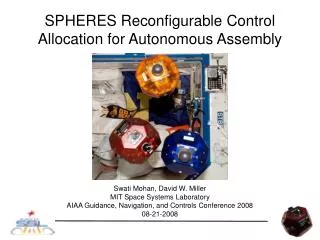
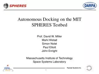
Autonomous Docking on the MIT SPHERES Testbed. Prof. David W. Miller Mark Hilstad Simon Nolet Paul Elliott John Enright Massachusetts Institute of Technology Space Systems Laboratory. Agenda. Flight status and operations plan. State Estimation. Guest Scientist Program. Docking.

E N D
Autonomous Docking on the MIT SPHERES Testbed Prof. David W. Miller Mark Hilstad Simon Nolet Paul Elliott John Enright Massachusetts Institute of Technology Space Systems Laboratory
Agenda Flight status and operations plan State Estimation Guest Scientist Program Docking Autonomy
Flight Status • Safety 0-1-2 Review: Completed - Jan, 2002 • Critical Design Review: Completed - Feb, 2002 • Crew Procedure and Display (GUI): On-going • Flight Engineering Hardware: June 2002 • KC-135 Test of Engineering Hardware: July 2002 • KC-135 Flight Experiment: July 29 - Aug 2, 2002 • Flight Hardware: October 2002 • Safety 3 Review: October 2002 • Crew Training: December 2002 • Manifested on ISS 12A.1 (STS-116): June 2003 • Re-supply flight on ISS 13A.1 (STS-118): August 2003 • Return flight on ISS 15A (STS-119): January 2004
Operational Scenarios • Mode 1: Single satellite operations examples • Long term station-keeping • Minimum propellant maneuvers through pre-determined profiles • Isolated multidimensional rotation, multidimensional translation • Combined rotation & translation • Modes 2 and 3: Multiple satellite operations examples (two or three satellites) • Docking • Topological orientations • Independent control • Collision avoidance • Hierarchical control (leader-follower) • Distributed control (consensus) • SPHERES will operate in United States Operational Segments (USOS) only • Ideal test area is 6’ x 6’ x 6’ • Most likely will operate in a 5’ x 5’ x 10’ volume in U.S. Node, illustrated below.
Crew Operational Responsibilities Take down and stow equipment Prepare test area (position US beacons) Unstow equipment Load tanks & battery packs into satellites Upload protocols from laptop to satellites Run protocols from laptop NO YES Satellites out of gas / power? Test session over? YES NO
Typical Test Session Flowchart Each sphere calculates position and attitude using PADS transmitters Transfer protocol/commandsvia wireless link ISS Laptop Performs formation flying maneuver Uplink protocols to OPS LAN from ground prior to SPHERES operations Control Loop Data Acquisition Appropriate thrusters fire Downlink experiment data to ground after SPHERES operations ISS Laptop
Mission Logistics • Operation time • Allocated 20 hours operation time • Nominally ten 2-hour sessions, at two-week intervals • Setup and tear down not included in total operations time • Initial stowage requirements • Three spheres • Five ultrasound beacons • Laptop transmitter • Consumables • Current estimate: 94 CO2 tanks and 87 battery packs • Spares are TBD • Stowage location • Stowage likely to be in Cargo Transfer Bags (CTBs) in the Multi-Purpose Logistics Module (MPLM) • May be stored in middeck locker if necessary
Preliminary Graphical User Interface Status window Main interface window Command window
Avionics Upgrades • Upgrade from C40 to C6701 • Increase computational power by one order of magnitude • Expansion port for add-on hardware • Increase communications bandwidth • 916.5 and 868.35 MHz • 115.2 kbps
Program Schedule • Final year-1 meeting / Kickoff meeting for year-2 6/02 • Transition to flight hardware 6/02 • Documentation and coding of the algorithms 7/02 • Experiments Development 11/02 • Testing 12/02 • Demonstrations on the SPHERES testbed 2/03 • Final year-2 meeting 5/03
Agenda Flight status and operations plan State Estimation Guest Scientist Program Docking Autonomy
Algorithm Classification Operational mode Health status Autonomy Plan generation Optimal docking Control Closed-loop control Metrology State estimation
200 150 z [cm] 100 50 0 250 200 150 0 x [cm] 100 50 100 50 150 y [cm] 200 0 Position & Attitude Determination • Beacon locations define operational volume • Time-of-flight ranging • “Master” sphere requests a global update by emitting an infrared (IR) flash. • Beacons respond to IR flash with ultrasonic pulses. • Spheres turn off thrusters to listen for the ultrasonic pulses. • Receivers on each sphere record the times when the ultrasonic pulses are received. • Spheres compute ranges based on the ultrasound times of flight. • Position and attitude are calculated from ranges.
PADS Hardware • PADS receiver boards • Two ultrasound receivers • Two infrared transmitters • One infrared receiver • Two receiver boards per side on each of six sides. • Four ultrasound receivers per side • Ultrasound beacon • One infrared receiver • One ultrasound transmitter • One PIC microprocessor • Inertial measurement unit • Three single-axis gyroscopes • Three single-axis accelerometers US receiver IR transmitter IR receiver US transmitter Gyroscope Accelerometer
State Estimate Propagation • State propagation occurs at the local sensor sample frequency (50 Hz). • Gyroscopes (flight sphere and prototype sphere) • Accelerometers (flight sphere only) • Estimate can be propagated using sensors or a dynamic model. • Provides redundancy. • Can be used to test autonomy algorithms for automatic reconfiguration in case of (simulated) sensor failure.
State Estimate Update • Range measurements are used to update the state estimate at approximately 1-2 Hz. • Prototype currently uses an optimal memoryless attitude algorithm and a Kalman filter for position and velocity • Attitude update requires rough position information. • Only lightly coupled, simplifying PADS algorithm development. • Fully coupled position, velocity, attitude Kalman filter will be added later.
PADS Testing • The “PADS sphere” was fabricated to allow development of PADS algorithms on flight-like hardware without the need to interface with other subsystems. • PADS sphere components: • 12 PADS receiver boards • Xilinx Spartan II FPGA development board linked directly to a laptop using USB cable • A 3-D testing arena is used for on-going test and development • Successfully tested in the ISS U.S. Node mockup at JSC, verifying the system in a more flight-like environment. PADS sphere
On-board US beacon US receivers Sensor Suite Simulation • A single ultrasound beacon is mounted on each sphere, to be used for direct ranging between the vehicles. • Direct measurements can be used to find range and a direction vector from the receiving sphere to the transmitting sphere. • Useful for docking maneuvers. • Relative roll angle is unobservable through direct inter-sphere ranging. • Complete relative state determination requires the use of the external beacons for determination of roll angle. • The spheres estimate both position and attitude in the global reference frame. • Different space missions use different types of sensors. • The state estimate can be used to simulate measurements from other sensor types. • Sphere-to-sphere communication of state estimates can be used to create simulated relative measurements.
Agenda Flight status and operations plan State Estimation Guest Scientist Program Docking Autonomy
GSP interface delivery Guest Scientist source code MIT SPHERES team Deliver to MIT SPHERES team GSP simulation GFLOPS simulation Laboratory testbed International space station Guest Scientist at local facility SPHERES Guest Scientist Program • Guest Scientist Program goal: To provide sufficient information to allow remote investigators to independently design, code, and debug control and autonomy algorithms for use on the SPHERES testbed. • The GSP development process consists of four parts: • GSP SPHERES simulation (at local facility) • GFLOPS SPHERES simulation (at MIT) • Laboratory testbed (at MIT) • International Space Station • Feedback is provided to guest scientists at each step. • GSP interface consists of: • GSP interface document • GSP SPHERES simulation • Matlab data reduction script
Propulsion interrupt (1 kHz) Timekeeping Control interrupt (25 Hz max) Tank estimate Maneuver planning and control algorithms Thrusters Battery estimate PADS hardware Disable thrusters for global update STL communications Laptop IR interrupt IR flash Housekeeping IR receive Synchronize clocks STS communications Inertial sensors Physical dynamics Inertial sensors readings State propagation State estimate FPGA Background process PADS interrupt ultrasound sensors PADS Global data collection State update Other spheres Ultrasound beacons Flight Software Design • Background process: • Send and process received communications data. • Perform state update. • Control interrupt • Determine state error. • Apply control law. • Set thruster on-times. • Propulsion interrupt • Increment clock. • Turn on/off thrusters. • PADS interrupt • Sample inertial sensors • Propagate state estimate
Control Interfaces • Standard Control Interface • Facilitates rapid test development using modular algorithm blocks with pre-defined inputs and outputs. • Modular, high-level design allows for rapid maneuver development and simple tracking of code changes • Individual modules may be replaced without the need to write new code to perform the functions handled by the other modules. • Pre-defined inputs and outputs for each module type ensure that old code can be reused, while allowing flexibility in the design of individual modules. • Direct Control Interface • Contents of the control interrupt and background process are replaced by the guest scientist with custom code. • Custom Control Interface • Completely customizable by the end user
Global Variables Command any needed information Maneuver profile desired state vector Determine state error state estimate vector state error vector Controller Repeat while termination flag is FALSE Apply control law Force and torque control array Mixer Set thruster on-times thruster array Terminator If termination condition is met, set maneuver termination flag Standard Control Interface • A simple maneuver consists of four parts: • Command • Use desired maneuver plan or desired trajectory to calculate state error • Controller • Apply control law to determine desired force and torque • Mixer • Use thruster geometry and actuation profiles along with deadband rules to determine thruster on-times • Terminator • When a particular condition is met, the maneuver is terminated and the maneuver number is incremented.
GSP SPHERES Simulation • The GSP SPHERES simulation is delivered as part of the GSP Interface. • Used for in-house development of flight code by guest scientists • Simulation contains all of the flight code except for low-level functions that directly access hardware. • Software developed on the GSP simulation can be used without modification on the testbed. • Completely stand-alone • No specialized hardware required • Software requirements • Windows 2000 • Microsoft Visual C++ 6.0 • Described in detail in the GSP Interface Document.
Flight Software Simulator Thruster Simulator Thrust Forces, Torques Wrapper code Wrapper code SPHERES code SPHERES code Dynamics Propagator State, etc. SPHERE 1 SPHERE 2 State Metrology Simulator Metrology FSW HW Simulator HW Simulation architecture and support hardware: Payload Engineering Operations Eight Embedded CPUs Support PCs GFLOPS SPHERES Simulation • Generalized FLight Operations Processing Simulator (GFLOPS) • Captures data handling issues of computationally demanding missions • Flexible, traceable components • Software partitioning enhances simulation honesty • Validate algorithms before implementation on SPHERES hardware • Flight code exchangeable with • GSP simulation • Testbed hardware • Long-duration 6 DOF testing • Higher fidelity than GSP simulation • Real-time operating system
GFLOPS Simulation Results Compare simulation results to laboratory air-table performance: rotation test translation test • Simulation results are similar to those of laboratory testbed in overall motion • Sensor variability is difficult to reproduce on small scales
Simulation Visualization Formation flying simulation Docking simulation
Agenda Flight status and operations plan State Estimation Guest Scientist Program Docking Autonomy
Advanced Cooperation Uncooperative Slow Speed Collision Medium Cooperation Type of docking Knowledge Control Enabled Comm Capability Position Orientation Attitude Position SPHERES X X X X X X ---- X X ---- ---- X X X X ---- ---- ---- ---- ---- Types of docking Target spacecraft capabilities
Docking Goals Specific Objectives: • Validate capability to performing different types of autonomous docking • Validate capability to implement autonomous path planning • Develop confidence in using autonomous docking algorithms Overall Project Goal: To develop a generalized code capable of autonomously performing different types of docking
Autonomous Docking Process Benchmark Maneuver: Uncooperative Docking Optimal Path Planning Start Maneuver Trajectory Tracking Analyze Impact of Disturbances Replan Trajectory if Necessary Perform Docking
Selected Docking Paths Autonomous Path Planning Position Scenarios Orientation Scenarios Autonomous Docking Process Benchmark Maneuver: Uncooperative Docking Optimal Path Planning
Position Scenarios 2-D Position Planning • To reach a target while avoiding obstacles • 2 approaches considered: • Perpendicular to the axis of rotation of a tumbling spacecraft • Straight approach after the passage of solar panels 1. 2.
Late alignment of the docking ports required Orientation Scenarios 2-D Orientation Planning • To properly orient the docking ports • To orient the thruster firings optimally in order to save fuel • 3 approaches considered: 1. Docking Ports Always Facing Each Other 2. No Rotation for the SPHERE Coming In 3. Maintain Thrusters Oriented Along Primary Thruster Axis 1. 2. 3.
Docking Ports Always Facing Each Other No Rotation for the SPHERE Coming In Maintain Thrusters Oriented Along Primary Thruster Axis Perpendicular to the axis of rotation 0.193 m/s 0.194 m/s 0.151 m/s Approach After Panel Passage N/A 0.028 m/s 0.021 m/s 2-D Simulation Results Computed minimum delta-V required Orientation Position Position planning is more critical than orientation planning in terms of propellant consumption
Autonomous Path Planning Proposed Solutions: • Glideslope Algorithm • Find autonomously non-optimal trajectories • Proven technology (Apollo, Shuttle) • Good sensor visibility • Minimal computation required • Mixed-Integer Linear Programming • Find propellant-optimal trajectories for spacecraft subjected to avoidance requirements • Collision Avoidance • Plume Impingement • The method requires intense computation Prof. Jon How, Arthur Richards, Tom Schouwenaars MIT Space Systems Laboratory
Glideslope Algorithm • Follow straight line to target • Use fixed number of equally-spaced burns • Simulation includes measurement noise & model error (angular velocity of the target is known approximately) (Hablani et al, 2001 GNC)
MPC/MILP I • Mixed Integer Linear Programming (MILP): solves optimal trajectory problems with avoidance • Model Predictive Control (MPC): repeated solution of optimal trajectory problem • V 62% less than glideslope • Not very good sensor visibility (Richards & How, 2002)
MPC/MILP II • Added visibility ‘cone’ to enforce line of sight to port • V still 57% less than glideslope • On-going research: • Plume impingement • Inspections/fly-bys (multiple waypoints) • Robustness
Autonomous Docking Process Benchmark Maneuver: Uncooperative Docking Optimal Path Planning Start Maneuver Trajectory Tracking Analyze Impact of Disturbances Replan Trajectory if Necessary Perform Docking
PD Tracking Bounding Box Tracking LQR Tracking Autonomous Docking Process Benchmark Maneuver: Uncooperative Docking Trajectory Tracking
Acceptable position error Path x Target Trajectory Tracking • SPHERES hardware limitations: • Dead band (depend on the fluctuation of the state estimations) • Minimum impulse bit (~ 0.002 Ns) • Regulation will lead to a slow speed oscillation around desired state • Early regulation • Late regulation Propellant-expensive oscillations along the path (PD tracking system) Propellant-expensive thruster firings at the end of the docking maneuver • State error boundary • Compromise: linearly decreasing acceptable state error
Tracking Algorithm Selection • Linear Quadratic Regulator type tracking system • Plant: • Cost: • Manipulating weighting matrices (Rxx, Ruu, Ptf) allows to obtain a path with linearly decreasing acceptable state errors • Bounding box type tracking system • Bounding box: desired “state zone” so that no error corrections are applied if spacecraft is located in that zone (its size varies along the path) • Replanning occurs when one of the state reaches its max acceptable error from the nominal desired state • Replanning involves finding a new path between current states and final desired states
Delta-V Final Position Error Final Velocity Error 87 mm/s 10 mm 0.15 mm/s Delta-V Final Position Error Final Velocity Error 57 mm/s 3.2 mm 0.18 mm/s Delta-V Final Position Error Final Velocity Error 53 mm/s 10.6 mm 2.66 mm/s Tracking Schemes Comparison • PD tracking • Bounding box tracking Good Compromise • LQR tracking
Bounding Box Tracking Simulation • Noise (thruster noise) was implemented in the simulations • Accuracy of corrective thruster firings is decreased • Need more corrective thruster firings near bounding box boundary • Establish an early target waypoint to avoid that zone Acceptable position error Desired Path x Target Waypoint ¼ of Desired Path Length
Laboratory Experiments • Docking Control • 2DOF Position Control (X,Y) • 1DOF Attitude Control (Z axis rotation) • Master/Slave Control, Uncooperative Docking • Master holds position and attitude, transmits data to slave at 10Hz • Slave translates towards master via path following and attitude hold • Initial path created from initial separation • Path updated during translation based on master’s residual motion
Autonomous Docking Process Benchmark Maneuver: Uncooperative Docking Optimal Path Planning Start Maneuver Trajectory Tracking Analyze Impact of Disturbances Replan Trajectory if Necessary Perform Docking
Autonomous Docking Process Benchmark Maneuver: Uncooperative Docking Analyze Impact of Disturbances Replan Trajectory if Necessary Perform Docking
Agenda Flight status and operations plan State Estimation Guest Scientist Program Docking Autonomy