Download
1 / 28
280 likes | 467 Vues
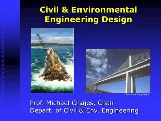
Civil & Environmental Engineering Design. Prof. Michael Chajes, Chair Depart. of Civil & Env. Engineering. Photo by Doug Baker. Webster’s Definition of Design. “to create, fashion, execute, or construct according to plan,” and “to devise for a specific function or end.”.

E N D
Civil & Environmental Engineering Design Prof. Michael Chajes, Chair Depart. of Civil & Env. Engineering Photo by Doug Baker
Webster’s Definition of Design “to create, fashion, execute, or construct according to plan,” and “to devise for a specific function or end.”
Webster’s Definition of Design “to create, fashion, execute, or construct according to plan,” and “to devise for a specific function or end.”
Design Constraints Safe PE code of ethics states: “Engineers, in the fulfillment of their professional duties, shall hold paramount the safety, health, and welfare of the public.” Functional Economic Aesthetically pleasing No one solution!
Design Example Design a shelf for you dorm room Wood 1” x 8” x 6’ Wall
Design Example Tension Strut Design a shelf for you dorm room
Design Example Design a shelf for you dorm room Compression Strut
LOADS W books = 50 lbs/ft W total = 6 x 50 = 300 lbs Each strut (2 total) = 150 lbs Factor of safety = 2 W books/strut = 300 lbs F=ma, a=0, SF=0 Vertical direction 0 = - 300 lbs + (3/5) F strut F strut = (300) x (5/3) F strut = 500 lbs Design Tension StrutMode of Failure: Fracture 10” 6” 8” F strut Free Body Diagram F shelf W books/strut
Design Tension StrutMode of Failure: Fracture STRUT SIZE Stress = Force/Area Use steel rods Stress Ultimate = 36,000 lb/in Area = Force/Stress = 300/36,000 Area required = 0.008 in 10” 6” 2 8” 2 2 2 A = p r = p d / 4 0.008 = p d / 4 d = 0.10 in. 1/8 = 0.125 in. 2 1/8” diameter rod
LOADS W books = 50 lbs/ft W total = 6 x 50 = 300 lbs Each strut (2 total) = 150 lbs Factor of safety = 2 W books/strut = 300 lbs F=ma, a=0, SF=0 Vertical direction 0 = - 300 lbs + (3/5) F strut F strut = (300) x (5/3) F strut = 500 lbs Design Compression StrutMode of Failure: Fracture 8” 6” 10” Free Body Diagram F shelf F strut W books/strut
Design Compression StrutMode of Failure: Fracture STRUT SIZE Stress = Force/Area Use metal rods Stress Ultimate = 36,000 lb/in Area = Force/Stress = 300/36,000 Area required = 0.008 in 2 8” 6” 2 10” 2 2 A = p r = p d / 4 0.008 = p d / 4 d = 0.10 in. 1/8 = 0.125 in. 2 1/8” diameter rod
P Design Compression StrutAnother Mode of Failure: ? 8” 6” 10” steel rod P
Pcr Euler Buckling Formula Pcr = p EI / L Pcr = Buckling load E = Material stiffness I = Moment of inertia L = Length Pcr = 500 lbs E = 29,000,000 lb/in I rod = pr / 4 L = 10 in. Design Compression StrutMode of Failure: Buckling 2 2 8” 6” 10” 2 4 Pcr
Pcr Design Compression StrutMode of Failure: Buckling Strut Size Pcr = p EI / L 500=(p )(29,000,000)(pr / 4)/(10 ) r = 0.12, d = 0.24, 1/4 = 0.25 in. 8” 2 2 6” 2 2 4 10” 1/4” diameter rod Pcr
10” 1/8” diameter rod Strength * Strut Design Summary 6” 8” 6” 1/8” diameter rod Strength 10” 1/4” diameter rod Stability * What did we not consider (failure modes, design criteria)?
Bridge Design Bridge Location http://travel.yahoo.com/p-travelguide-577578-map_of_delaware-i Case Study: The New Indian River Inlet Bridge
Reason for Replacement: Scour Scour holes greater than 30 m deep
Specificationsfor the New Bridge • Because the piers of the existing Indian River Inlet bridge are in the tidal inlet, scour has become a serious problem • A new bridge will be built by 2010 to replace the existing bridge • The bridge span will be over 900 ft. in order to span the inlet http://www.deldot.gov/static/projects/indian_river_bridge/replacement.shtml
Preliminary Design Courtesy of FIGG Engineering Group
Preliminary Design Courtesy of FIGG Engineering Group
Preliminary Design Courtesy of FIGG Engineering Group
Design Constraints/Decisions How many can you list?
How will it be constructed • How will it be inspected • How will it be maintained • How will it be financed Design Constraints/Decisions Location of bridge Span of bridge Number of lanes Alignment of roadway Type of bridge Bridge aesthetics Type of foundation Scour protection Environmental impact Materials to be used Loadings to consider Size of members
West Point Bridge Design Program http://bridgecontest.usma.edu
Protecting a Bridge with a Breakwater Plan View Elevation View Bridge Roadway Sandbar Water Surface Bridge Roadway Pier 4.5 in. Sandbar 26 in. 12 in. Breakwater 1 30 Brick Waves 2.25 in. 8 in. 3.5 in.