NEW Ionization Chamber Technology
NEW Ionization Chamber Technology. Anne Dabrowski Results on behalf of Mayda Velasco’s Hardware Research group . P. Ball 3 , A. Darowski 1 , G. Graham 3 , C. Kendziora 2 , F. Krueger 2 G. Tassotto 2 , G. Ünel 1 , M. Velasco 1

NEW Ionization Chamber Technology
E N D
Presentation Transcript
NEW Ionization Chamber Technology Anne Dabrowski Results on behalf of Mayda Velasco’s Hardware Research group. P. Ball 3, A. Darowski 1, G. Graham 3, C. Kendziora 2, F. Krueger 2 G. Tassotto 2,G. Ünel 1, M. Velasco 1 1 Northwestern University,2 Fermilab,3 Richardson Electronics Lunch Bag Seminar 1 May 2002
Why the need for new Hardware? • Modern High Energy Experiments • High intensity beams > 1011 particles/ micro second • Radiation Hard • Once-off calibration • Monitor beam line position / background particle flux Northwestern High Energy Physics
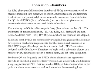
Solution: • Ceramic radiation hard ionization chambers. • Either Gas sealed or Vacuum – SEM (secondary emission monitor) • Q = I * d * e*A * n * M current read by chamber M – multiplication factor (~1) N – tot num of ion/electron pair/cm (8 for He at atm 98 for Ar at 1 atm) A – elecrode area (cm2) (1 cm2) I – beam intensity (cm-2 s-1) (<1011 cm-2 s-6) d – gap size (cm) (~1mm) e – electron charge Northwestern High Energy Physics
Basic Description of Design Northwestern High Energy Physics
Basic Chamber Design Northwestern High Energy Physics
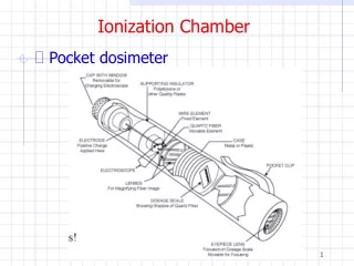
Engineering drawing • Tolerances: • Gap = 1mm +/- 0.001” • guard-to-collector = 0.5 mm+/- 0.002” • Flatness 0.001” Northwestern High Energy Physics
SIC prototypes Northwestern High Energy Physics
Timeline for Design Development • 2000 Richardson Electronics (REL) made Glass Chambers (Inspired by V. Falaleev Design). • Detection observed • Design studies • Change to ceramic because of high tolerances • Ceramic design • Electrode changed from round edges to edges square D1 – D2 • Flat for signal collector & guard ring. • Multiple chambers produced (7 in all) • gas refilling tested. • Found occasional shorts on due to metal filings inside the chamber…tooling redesign. • Believe have the final design • (testing by producing several chambers….already under construction). • successful • mass production will start at the rate of 10 chambers/week. Northwestern High Energy Physics
How do they Behave ? Northwestern High Energy Physics
Radiation Physics Calibration Facility (RPCF)Photon Emission 424 R/hr • Check chamber quality • Plateau, ionization response, reproducibility • Lead to design improvements • Determined operational modes • operational voltage, gain voltage, gas type • Do pre-calibration before operating in other facilities. Northwestern High Energy Physics
Radiation Physics Calibration Facility (RPCF,FNAL) “Flat mounting” • Two new Cs137 sources: • Max:1600 Rad/Hr • The old source was • 424 Rad/Hr “Side Mounting” Northwestern High Energy Physics
Results (RPCF) Note Slope !! Electrode edges Northwestern High Energy Physics
What Changed?Design 1 vs. Design 2 The electrode edge … Curved Flat Effected slope of plateau … reduced by ~ 70 % Northwestern High Energy Physics
Signal > Electrode area Results D2 vs. D4 Northwestern High Energy Physics
Setup to test chambers at the RPCF– pre-calibration for all SICs • Investments: A Keithly • electrometer • Sensitivity 2 nC • Resolution of 0.1 pC • Bias current of < 3fA • Output of electrometer via GPIB to computer running LabView to a data file. • Procedure almost automatic Good for grad students when calibrating in the summer Northwestern High Energy Physics
Chamber Characterization show no radiation damage after XX protons Chamber filled with He for more than a year Reproduce calibrations No change… Northwestern High Energy Physics
Summary of RPCF Results: • Good reproducibility • Can measure both small and large currents. • Keithley Electrometers and Powers Supplies allows to do good measurements of knee of plateau need to test gas quality of chambers… no degradation see so far. • LABview DAQ – user enter customized measurement parameters – automated DAQ • Slopes good – but not quite flat… we believe we understand it.
Tests at ATF (BNL) low energy electron beam No saturation below 8*109/p/cm2 Northwestern High Energy Physics
Booster (FNAL) proton source ~1e9 to 1e12 1mm Wire Chamber & SIC SIC Only New Toroid +chamber for Flux measurement & Longitudinal movement for alignment Old Toroid only for Flux measurement
Booster (FNAL) HaloHigh intensity ~ 1e9 proton source1.5 ms per spill … halo see 1/100 of total beam ONLINE OFFLINE
Booster (FNAL) Plateau in the beam (1.8e11)---saturation (same effects present with design 4) shortens plateau—space charge Northwestern High Energy Physics
Booster (FNAL) – Intensity Scan SEM-like SIC-like Clear … Saturation No saturation even At 1012 ppp (10-5 torr) Northwestern High Energy Physics
Beam Profile from Wire chamber Need to repeat With vertical movement Beam Moved Chamber see about 40% Of the beam Northwestern High Energy Physics
Summary of results from Booster • Saturate above e11 in SIC-mode, but no saturation in SEM-mode. • When making plateaus: gain observed at 200 V in the beam center, but not seen at 350 V in the “halo” like in the RPCF tests • use SWIC electronics for both low and high currents just change capacitors • So far no signs of radiation damage … or helium leakage • To do… add vertical movement to get proper alignment. Northwestern High Energy Physics
Secondary Emission Monitor– SIC chamber in vacuum • Getter - Place a strip of barium under the collector and activate it at about 1000 degree C. • Ion Bombardment - Apply a voltage across the electrodes while pumping for reducing atmosphere of H2. • Richardson used this process on vacuum tubes to 10-8 torr This look like a very promising way of operating The chambers for >1011 ppp Northwestern High Energy Physics
Permeation Test– test run for 3-4 days … Helium is not leaking…. • The ion chamber was then put in side of a small vacuum chamber and tested using a Dupont Mass Spectrometer leak detector the total leak rate was found to less than 2X10 –10 STD CC P/S. • Then the temperature was raised slowly to 100 degree C. • Max leak rate < 40X10 –10 STD CC P/S Northwestern High Energy Physics
Conclusion Northwestern High Energy Physics