Download

1 / 32
320 likes | 353 Vues
Learn about transformers, their classification, primary and secondary windings, ideal transformers, impedance transformation, and the theory of operation of single-phase real transformers.

E N D
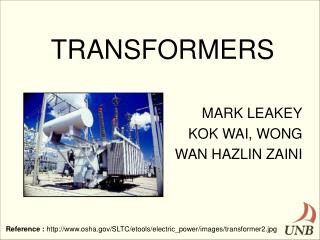
Transformers Presented by : Mr. Y.S.Bais
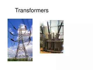
Introduction • A transformer is a device that changes ac electric power at one voltage level to ac electric power at another voltage level through the action of a magnetic field. • There are two or more stationary electric circuits that are coupled magnetically. • It involves interchange of electric energy between two or more electric systems • Transformers provide much needed capability of changing the voltage and current levels easily. • They are used to step-up generator voltage to an appropriate voltage level for power transfer. • Stepping down the transmission voltage at various levels for distribution and power utilization.
Transformer Classification • In terms of number of windings • Conventional transformer: two windings • Autotransformer: one winding • Others: more than two windings • In terms of number of phases • Single-phase transformer • Three-phase transformer • Depending on the voltage level at which the winding is operated • Step-up transformer: primary winding is a low voltage (LV) winding • Step-down transformer : primary winding is a high voltage (HV) winding
Primary and Secondary Windings A two-winding transformer consists of two windings interlinked by a mutual magnetic field. • Primary winding – energized by connecting it to an input source • Secondary winding – winding to which an electrical load is connected and from which output energy is drawn. Primary winding Secondary winding
Ideal Transformers An ideal transformer is a lossless device with an input winding and an output winding. It has the following properties: • No iron and copper losses • No leakage fluxes • A core of infinite magnetic permeability and of infinite electrical resistivity • Flux is confined to the core and winding resistances are negligible
Ideal Transformers An ideal transformer is a lossless device with an input winding and an output winding. fM The relationships between the input voltage and the output voltage, and between the input current and the output current, are given by the following equations. In instantaneous quantities
Ideal Transformers In rms quantities Np: Number of turns on the primary winding Ns: Number of turns on the secondary winding vp(t): voltage applied to the primary side vs(t): voltage at the secondary side a: turns ratio ip(t): current flowing into the primary side is(t): current flowing into the secondary side
Derivation of the Relationship …………….. (1) …………….. (2) Dividing (1) by (2) ………………......……….. (3) From Ampere’s law …………………..……….. (4) Equating (3) and (4) ………………….. (5)
Power in an Ideal Transformer Real power P supplied to the transformer by the primary circuit Real power coming out of the secondary circuit Thus, the output power of an ideal transformer is equal to its input power. The same relationship applies to reactive Q and apparent power S:
Is Ip ZL Vp Vs Is Ip Z’L Vp Vs Impedance Transformation through a Transformer Impedance of the load: ZL= Vs/IsThe impedance of the primary circuit: Z’L= Vp/Ip = (aVs)/(Is /a) = a2 (Vs/ Is) = a2 ZL
Example 1 A 100-kVA, 2400/240-V, 60-Hz step-down transformer (ideal) is used between a transmission line and a distribution system. • Determine turns ratio. • What secondary load impedance will cause the transformer to be fully loaded, and what is the corresponding primary current? • Find the load impedance referred to the primary.
Solution to Example 1 • Turns ratio, a = 2400 / 240 = 10 b) Is= 100,000/240 = 416.67 A Ip= Is /a = 416.67 / 10 = 41.67 A Magnitude of the load impedance ZL = Vs/Is= 240/416.7 = 0.576 ohm • Load impedance referred to the primary Z’L = a2*0.576 = 57.6 ohm
Theory of Operation of Single-Phase Real Transformers Leakage flux: flux that goes through one of the transformer windings but not the other one Mutual flux: flux that remains in the core and links both windings
Theory of Operation of Single-Phase Real Transformers fp: total average primary flux fM : flux linking both primary and secondary windings fLP: primary leakage flux fS: total average secondary flux fLS: secondary leakage flux
Magnetization Current E1 When an ac power source is connected to a transformer, a current flows in its primary circuit, even when the secondary circuit is open circuited. This current is the current required to produce flux in the ferromagnetic core and is called excitation current. It consists of two components: 1. The magnetization currentIm, which is the current required to produce the flux in the transformer core 2. The core-loss currentIh+e, which is the current required to make up for hysteresis and eddy current losses
Ic Excitation current, Io E1 qo Magnetization current IM (current required to produce flux in the core) Core-loss current Ih+e (current required to make up for hysteresis and eddy current losses) IM Io f The Magnetization Current in a Real Transformer When an ac power source is connected to the primary of a transformer, a current flows in its primary circuit, even when there is no current in the secondary. The transformer is said to be on no-load. If the secondary current is zero, the primary current should be zero too. However, when the transformer is on no-load, excitation current flows in the primary because of the core losses and the finite permeability of the core. IM is proportional to the flux f Ic = Ih+e = Core loss/E1
The Equivalent Circuit of a Transformer The losses that occur in transformers have to be accounted for in any accurate model of transformer behavior. 1. Copper (I2R) losses. Copper losses are the resistive heating losses in the primary and secondary windings of the transformer. They are proportional to the square of the current in the windings. 2. Eddy current losses. Eddy current losses are resistive heating losses in the core of the transformer. They are proportional to the square of the voltage applied to the transformer. 3. Hysteresis losses. Hysteresis losses are associated with the rearrangement of the magnetic domains in the core during each half-cycle. They are a complex, nonlinear function of the voltage applied to the transformer. 4. Leakage flux. The fluxes which escape the core and pass through only one of the transformer windings are leakage fluxes. These escaped fluxes produce a self-inductance in the primary and secondary coils, and the effects of this inductance must be accounted for.
The Exact Equivalent Circuit of a Transformer Modeling the copper losses: resistive losses in the primary and secondary windings of the core, represented in the equivalent circuit by RP and RS. Modeling the leakage fluxes: primary leakage flux is proportional to the primary current IP and secondary leakage flux is proportional to the secondary current IS, represented in the equivalent circuit by XP (=fLP/IP) and XS (=fLS/IS). Modeling the core excitation:Im is proportional to the voltage applied to the core and lags the applied voltage by 90o. It is modeled by XM. Modeling the core loss current:Ih+eis proportional to the voltage applied to the core and in phase with the applied voltage. It is modeled by RC.
The Exact Equivalent Circuit of a Transformer Although the previous equivalent circuit is an accurate model of a transformer, it is not a very useful one. To analyze practical circuits containing transformers, it is normally necessary to convert the entire circuit to an equivalent circuit at a single voltage level. Therefore, the equivalent circuit must be referred either to its primary side or to its secondary side in problem solutions. Figure (a) is the equivalent circuit of the transformer referred to its primary side. Figure (b) is the equivalent circuit referred to its secondary side.
Determining the Values of Components in the Transformer Model • It is possible to experimentally determine the parameters of the approximate the equivalent circuit. An adequate approximation of these values can be obtained with only two tests…. • open-circuit test • short-circuit test
Circuit Parameters: Open-Circuit Test • Transformer's secondary winding is open-circuited • Primary winding is connected to a full-rated line voltage. All the input current must be flowing through the excitation branch of the transformer. • The series elements Rpand Xp are too small in comparison to RC and XM to cause a significant voltage drop, so essentially all the input voltage is dropped across the excitation branch. • Input voltage, input current, and input power to the transformer are measured.
Circuit Parameters: Open-Circuit Test The magnitude of the excitation admittance: The open-circuit power factor and power factor angle: The power factor is always lagging for a transformer, so the current will lag the voltage by the angle q. Therefore, the admittance YE is:
Circuit Parameters: Short-Circuit Test • Transformer's secondary winding is short-circuited • Primary winding is connected to a fairly low-voltage source. • The input voltage is adjusted until the current in the short-circuited windings is equal to its rated value. • Input voltage, input current, and input power to the transformer are measured. • Excitation current is negligible, since the input voltage is very low. Thus, the voltage drop in the excitation branch can be ignored. All the voltage drop can be attributed to the series elements in the circuit.
Circuit Parameters: Short-Circuit Test The magnitude of the series impedance: The short-circuit power factor and power factor angle: Therefore the series impedance is: It is possible to determine the total series impedance, but there is no easy way to split the series impedance into the primary and secondary components. These tests were performed on the primary side, so, the circuit impedances are referred to the primary side.
Example 2 The equivalent circuit impedances of a 20-kVA, 8000/240-V, 60-Hz transformer are to be determined. The open-circuit test and the short-circuit test were performed on the primary side of the transformer, and the following data were taken: Open-circuit test (on primary) Voc= 8000 V Ioc = 0.214 A Poc= 400 W Short-circuit test (on primary) Vsc= 489 V Isc = 2.5 A Psc = 240 W Find the impedances of the approximate equivalent circuit referred to the primary side, and sketch the circuit.
Transformer Voltage Regulation Because a real transformer has series impedance within it, the output voltage of a transformer varies with the load even if the input voltage remains constant. The voltage regulation of a transformer is the change in the magnitude of the secondary terminal voltage from no-load to full-load. Referred to the primary side
Transformer Efficiency Usually the efficiency for a power transformer is between 0.9 to 0.99. The higher the rating of a transformer, the greater is its efficiency.
Example 3 A single-phase, 100-kVA, 1000:100-V, 60-Hz transformer has the following test results: Open-circuit test (HV side open): 100 V, 6 A, 400 W Short-circuit test (LV side shorted): 50 V, 100 A, 1800 W • Draw the equivalent circuit of the transformer referred to the high-voltage side. Label impedances numerically in ohms and in per unit. • Determine the voltage regulation at rated secondary current with 0.6 power factor lagging. Assume the primary is supplied with rated voltage • Determine the efficiency of the transformer when the secondary current is 75% of its rated value and the power factor at the load is 0.8 lagging with a secondary voltage of 98 V across the load
PU System Per unit system, a system of dimensionless parameters, is used for computational convenience and for readily comparing the performance of a set of transformers or a set of electrical machines. Where ‘actual quantity’ is a value in volts, amperes, ohms, etc. [VA]base and [V]base are chosen first.
RS = 0.05 ohm XS= 0.06 ohm XM = 30,000 ohm RP= 32 ohm XP = 45 ohm RC= 250,000 ohm Example 4 A 20-kVA, 8000:480-Vdistribution transformer has the following resistances and reactances: The excitation branch impedances are referred to the high-voltage side. • Find the equivalent circuit of the transformer referred to the high-voltage side. • Find the per unit equivalent circuit of this transformer. • Assume that the transformer is supplying rated load at 480 V and 0.8 power factor lagging. What is this transformer’s input voltage? What is its voltage regulation? • What is this transformer’s efficiency under the conditions of part (c)?