Converting a Negative Decimal Number to the 2’s Complement Representation :
440 likes | 1.18k Vues
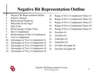
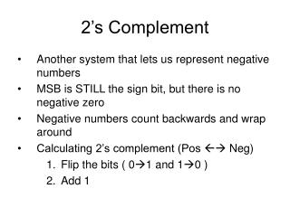
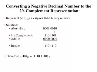
Converting a Negative Decimal Number to the 2’s Complement Representation : Represent (-18) 10 as a signed 8-bit binary number Solution: Abs(-18) 10 : 0001 0010 1’s Complement: 1110 1101 Add 1: + 0000 0001 Result: 1110 1110 Therefore, (-18) 10 = (1110 1110) 2. 1.

Converting a Negative Decimal Number to the 2’s Complement Representation :
E N D
Presentation Transcript
Converting a Negative Decimal Number to the 2’s Complement Representation: • Represent (-18)10 as a signed 8-bit binary number • Solution: • Abs(-18)10 : 0001 0010 • 1’s Complement: 1110 1101 • Add 1: + 0000 0001 • Result: 1110 1110 • Therefore, (-18)10 = (1110 1110) 2 1
Converting a Negative 2’s Complement Number to Decimal Representation: • Example: Represent (1001 1000)2 as a signed decimal number • Since MSB = 1 then the number is negative • Use signed conversion process • Solution: • The number: 1001 1000 • 1’s Complement: 0110 0111 • Add 1: + 0000 0001 • Result: 0110 1000 • Decimal 104 • -ve sign -104 • Therefore (1001 1000)2 = (-104)10
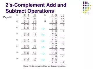
Addition of 8-bit (positive and negative) signed number: • Perform the addition: 8 + (-17) • Find the 2’s complement representation • (8)10 = 0000 1000 • (-17)10 = ??? • (17)2 0001 0001 • 1’s complement: 1110 1110 • Add 1 + 0000 0001 • Result 1110 1111 • Therefore (-17)10 = (1110 1111)2
Now • (8)10 0000 1000 • (-17)10 + 1110 1111 • Result (1111 0111)2 = (?) 10 • Convert the result to decimal representation: • 1111 0111 • take 1’s complement 0000 1000 • Add 1 + 0000 0001 • Result (0000 1001)2 = (+9)10 • Therefore, (1111 0111)2 is -9 in decimal
There are eight general-purpose registers, six segment registers, a register that holds processor status flags (EFLAGS), and an instruction pointer (EIP).
EAX ( Accumulator) is automatically used by multiplication and division instructions. It is often called the extended accumulator register for accumulating operands and results . • EBP ( Base) is used by high-level languages to reference function parameters and local variables on the stack (data on the stack). It should not be used for ordinary arithmetic or data transfer except at an advanced level of programming. It is often called the extended frame pointer register. • ECX ( Count) used as counter for string and loop operations. • EDX (Data) register that can be used for I/O pointer. • ESP stack pointer register. • ESI and EDI are used by high-speed memory transfer instructions. They are sometimes called the extended source index and extended destination index registers.
Status Flags • The Status flags reflect the outcomes of arithmetic and logical operations performed by the CPU. • They are the Overflow, Sign, Zero, Auxiliary Carry, Parity, and Carry flags. Their abbreviations are shown immediately after their names. • The Carry flag (CF) is set when the result of an unsigned arithmetic operation is too large to fit into the destination. • The Overflow flag (OF) is set when the result of a signed arithmetic operation is too wide (too many bits) to fit into the destination. • The Sign flag (SF) is set when the result of an arithmetic or logical operation generates a negative result.
The Zero flag (ZF) is set when the result of an arithmetic or logical operation generates a result of zero. • The Auxiliary Carry flag is set when an arithmetic operation causes a carry from bit 3 to bit 4 in an 8-bit operand. • The Parity flag sums the number of bits that are set in a number, and indicates whether the sum is odd or even.
Reserved Words • Assembly language has a list of words called reserved words. These have special meaning and can be used in their correct context. Reserved words can be any of the following: • Instruction mnemonics, such as MOV, ADD, or MUL, which correspond to built-in operations preformed by Intel processor, • Directives, which tell MAZM how to assemble programs. • Attributes, which provide size and usage information for variables and operands. Examples are BYTE and WORD. • Operators, used in constant expressions. • A complete list of MAZM reserved words will be found in Appendix D.
Identifiers • An identifier is a programmer chosen name. it might identify a variable, a constant, a procedure, or a code label. Keep the following in mind when creating identifiers: • They may contain between 1 and 247 characters. • They are not case sensitive. • The first character must be either a letter (A…Z, a…z ), underscore(_), $. Subsequent character may also be digits. • An identifier can not be the same as an assembler reserved word. • Example of identifiers • Var1 count $first • Max open
Directive • A directive is a command that is recognized and acted upon by the assembler as the program's source cod is being assembled. • Directives are being used for defining logical segments, choosing a model, defining variables, creating procedures, and so on. • Different capitalization of the same directive are assumed to be equivalent. For example the assembler does not recognize any • difference between .data, .DATA, and .Data. • Examples of directives are: • .Data ‘identifies the area of a program that contains variables’ • .code ‘ identifies the area of a program that contains instructions’ • A-name proc ‘identifies the beginning of procedures • It would take a very long time to learn all the directives in MAZM, • so we concentrate on the few that are most essential.
Comments • Comments as you probably know, are an important way for the writer of a program to communicate information about how the program works to the person reading the source code. • Comments can be specified by semicolon. • Example: • ;This line is coment; • For Block comments you can use COMMENT directive and a user specified symbol. • Example: • COMMENT & • This line is comment • this line is also comment • &
Program Template • TITEL Program Template • ; Program Description: • ; Author: • ; Creation Date: • ; Revisions: • ; Date: Modified by: • INCLUDE Irvine32.inc • .data • ; (insert variables here) • .code • main PROC • ; (insert executable instructions here) • exit • main ENDP • ; (insert additional procedure here) • END main
Example: TITLE Hello Program ; Program Description: This program will display Hello World message on the ; screen ; Author: Sahar Mosleh ; Creation Date: August 30, 2005 INCLUDE Irvine32.inc .data ; (insert variables here) prompt1 byte “Hello World”,0 ; Store the prompt1 in ; memory .code main PROC ; (insert executable instructions here) call clrscr ; clear the screen mov edx, offset prompt1 ; move the address of prompt to edx call writestring ; display the string that is stored at ;the address pointed by edx call crlf ; move the courser to next line exit main ENDP ; (insert additional procedure here) END main
Example: TITLE Print Integer ; Program Description: This program will display integer number 216543 on the ; screen ; Author: Sahar Mosleh ; Creation Date: August 30, 2005 INCLUDE Irvine32.inc .data ; (insert variables here) .code main PROC ; (insert executable instructions here) call clrscr ; clear the screen mov eax, 2156543 ; move the integer to eax call writeInt ; display the INT that is stored at eax call crlf ; move the courser to next line exit main ENDP ; (insert additional procedure here) END main
Example: TITLE Input Integer ; Program Description: This program will read integer from user and out put ;it on the screen ; Author: Sahar Mosleh ; Creation Date: August 30, 2005 INCLUDE Irvine32.inc .data ; (insert variables here) prompt1 byte “Please input an intege”,0 ; Store the prompt1 in ; memory .code main PROC mov edx, offset prompt1 ; move the address of prompt to edx call writestring ; display the string that is stored at ;the address pointed by edx call crlf ; move the courser to next line call Readint ;read the int from user and put it in eax call writeint ;display the content of eax exit main ENDP ; (insert additional procedure here) END main
LOOP Instruction • The LOOP instruction provides a simple way to repeat a block of statements a specific number of times. • ECX is automatically used as a counter and is decremented each time the loop repeats. • The Loop instruction involves two steps: • First, it subtracts 1 from ECX. • Next it compares ECX to zero. If ECX is not equal to zero, a jump is taken to the label identified instruction following the loop.
Example: • In the following example, we add 1 to EAX each time the loop repeats. When the loop ends, EAX = 5 and ECX = 0 • move eax,0 • move ecx5 • L1: • Inc eax • Loop L1 • A common programming error is to inadvertently initialize ecx to zero before beginning of the a loop. • If this happens, the Loop instruction decrements ECX to FFFFFFFFh, and the loop repeats 4,294,967,296 times.
Nested loops • When You must create a loop inside another loop, the problem arises of what to do with the counter in ECX. Saving the counter loop count in a variable is a good solution: • .data • count Dword ? • .code • Mov ecx,100 ;set outer loop counter • L1: • Mov count,ecx ;save outer loop counter • Mov ecx,20 ;set inner loop counter • L2: • : • : • Loop L2 ;repeat the inner loop count • Mov ecx, count ;restore outer loop count • loopL1 ;repeat the outer loop
Direct memory operand • Example: • .data • Var1 Dword 100h • : • : • .code • Mov eax var1
Indirect operand • An indirect operand can be any 32-bit general purpose register • ( EAX,EBX,ECX,EDX,ESI,EDI,EBP, and ESP) surrounded by brackets. The register is assumed to contain the offset of some data. For example ESI contains the offset of variable 1: • .data • Val1 byte 10 h • .code • Mov esi, offset val1 • If a move instruction uses the indirect operand as the source, the pointer in ESI is dereferenced and a byte is moved to EAX • Mov EAX [esi] Eax = 10 h • Or if the indirect operand is the destination operand, a new value is placed in memory at the location pointed to by the register: • Mov [esi] EBX
Array • Indirect operands are practically useful when dealing with arrays because an indirect operand’s value can easily be modified. • Similar to an array subscript, an indirect operand can point to different array elements. • For example, ArrayB contain three bytes. We can increment ESI and make it to point each byte, in order: • .data • ArrayB Byte 10h, 20h, 30h • .code • Mov esi, offset ArrayB • Mov a1, [esi] • inc esi • Mov a1, [esi] • Inc esi • Mov a1, [esi]
MASM has a number of operators that are effective tools for describing and addressing variables: • The Offset operator returns the distance of a variable from the beginning of it’s enclosing segment • The DUP operator generates a repeated storage allocation. • The TYPE operator returns the size ( in bytes ) of each element in an array • LENGHTOF operator returns the number of elements in an array • The SIZEOF operator returns the number of bytes used by an array initializer. • These operators are only a small subset of the operators supported by MASM. You may want to view the complete list in Appendix D.
Example: • ArrayB Byte 10h, 20h, 30h, 40h • ArrayDW Dword 1000,2000,3000,4000 • The pointers to the above arrays can be define as: • ptrB Dword ArrayB • PtrDW Dword ArrayDW
Example: • TITLE pointers • Include Irvine32.inc • .data • arrayB Byte 10h,20h,30h • arrayD Dword 4,5,6 • Ptr1 Dword arrayB ;pointer to arrayB • Ptr2 Dword arrayD ;pointer to arrayD • .code • main proc • mov esi, ptr1 ;move the address (pointer to arrayB) to esi • mov a1 [esi] • mov esi, ptr2 ;move the address (pointer to arrayD) to esi • mov eax,[esi] • Exit • Main ENDP • END main
.data • Buffer Byte 50 DUP(0) ;holds the characters • byteCount Dword ? ;holds counter for loop • .code • mov edx, offset buffer ;points to the buffer • mov ecx, (sizeof buffer)-1 ;specify max characters • call ReadString ;input the string • mov bytecount, eax
The These color constants are defined in Irvine32.inc. • The backgroung color must be multiplied by 16 before being added to the foreground color. • The following for example, defines yellow characters on a blue background • Yellow + (blue * 16) • Before calling SetTextColor, move the desired color to EAX • Mov eax, white + (blue*16) • Call setTextColor
Push operation • A 32-bit push operation decrements the stack pointer by 4 and copies a value into the location in the stack pointed to by the stack pointer. In the following figure, we push 0000005A on the stack: • Before the push, ESP=00001000h, and after the push, ESP=000000FFCh. ESP
Pop Operation • A pop operation removes a value from the stack and places it in a register or variable. After the value is popped from the stack, the stack pointer is incremented to point to the next highest location in the stack. The following diagram shows the stack before and after the value 00000002 is popped from the stack: 00001000 00000FFC 00000FF8 00000FF4 00000FF0
PUSH and PUP Instructions • PUSH Instruction: • The PUSH instruction first decrements ESP and then copies either a 16 or 32 bit source operand into the stack. A 16 bit operation causes the ESP to be decremented by 2. • A 32-bit operand causes ESP to be decremented by 4. There are Three instruction format • PUSH r/m16 • Push r/m32 • PUSH imm32 • If your program calls procedures from the Irvine 32 library, you should always push 32-bit values
Pop Instruction • The pop instruction first copies the contents of the stack element pointed to by ESP into a 16- or 32-bit destination operand and then increments ESP. • If the operand is 16 bits, ESP is incremented by 2. • if the operand 32 bits, ESP is incremented by 4. • POP r/m16 • POP r/m32
When you create a procedures other than your program's main procedure, end it with a RET instruction. It forces the CPU to return to the location from the procedure was called: • SumOf PROC • add eax,ebx • add eax,ecx ; Return the Sum value in EAX • Ret • SumOf ENDP • The startup procedure ( main Procedure) is a special case because it ends with the exit statement. When you INCLUDE Irvine 32.inc statement, exit Is an alias for a call EXITProcess, a MS_Windows function call that terminates the program.
Call and ret instructions • The CALL instruction call a procedures by directing the processor to begin execution at a new memory location. • The call instruction pushes its return address on the stack and copies the called procedure’s address into the instruction pointer (EIP) • When the procedures is ready it uses RET instruction to bring the Processor back to the point in the program where the procedure was called. By returning the address form stack to instruction pointer register EIP • The CPU always executes the instruction in memory pointed to by EIP
When the call instruction executes, The address following the call 00000025 is pushed on the stack and the address of MySub is located into as shown here: • Main proc • 00000020 Call MySub • 00000025 Mov ebx,eax • All the instruction in MySub execute up to its RET instruction. When the RET instruction executes, the value in the stack pointed by ESP is popped into EIP. • 00000040 MySub proc • Mov eax, edx • : • Ret • MySub ENDP
.data • Array Dword 10000h, 20000h, 30000h, 40000h, 500000h • theSum dowrd ? • Main PROC • mov esi, offset array ; ESI pointes to array • mov ecx, lenghtof Array ; ECX = array count • call ArraySum ; call calculate the sum • mov theSum,eax ; returned sum in EAX • call writeint ; print the sum • exit • main ENDP
;-------------------------------------------------------------------- ;-------------------------------------------------------------------- ArraySumPROC ; ;calculates and returns the array of 32-bit integers. ; recieives: ESI = Array ; ECX= number of elements in the array ; Returnes: EAX=Sum ;------------------------------------------------------------------- push esi ; Save ESI and ECX push ecx mov eax,0 ; Set Sum to Zero L1: add eax,[esi] ; add each integer to sum add esi,4 ; point to next integer loop L1 ; repeat for array size Pop ecx : restore ecx and ESI Pop esi ret ; Return sum in EAX ArraySum ENDP End mian
MLU Operations • The MUL instruction multiplies an 8-,16-,32-bits operand by either AL,AX,or EAX. The instruction format is: • MUL r/m8 • MUL r/m16 • MUL r/m32 • The result is in EDX and EAX . • EDX sets the flag register if it is not zero ( as the result of operation over flow situation is Eax carries the product of operation. • Will we go through the detail of multiplication and division instruction later on this course.
Example: • TITLE Multiply (AddSub2.asm) • ; This program Multiply two decimal numbers together. We need to put the first operand in eax, the ;second operand in another multi purpose register. The product goes to eax • ; Last update: 2/1/02 • INCLUDE Irvine32.inc • .data • val1 dword 10 • val2 dword 40 • .code • main PROC • mov eax,val1 ; eax=10 • mov ebx,val2 ; ebx=40 • mul ebx ; eax=ebx*eax • call writedec • exit • main ENDP • END main