SENSORS & GAS SYSTEMS
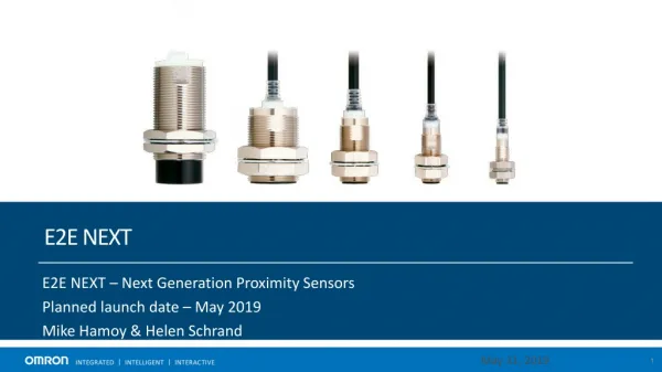
SENSORS & GAS SYSTEMS. SENSORS. Degital Sensors. Depth Wheel. Stroke Counter. Degital RPM. Analog sensors. HOOK LOAD. Use a pressure transducer and normally installed on the dead line anchor system exitation is 24DCV the out put is 4 - 20 ma. Analog sensors. STAND PIPE PRESSURE.

SENSORS & GAS SYSTEMS
E N D
Presentation Transcript
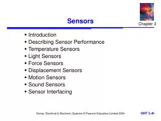
Degital Sensors • Depth Wheel. • Stroke Counter. • Degital RPM.
Analog sensors • HOOK LOAD. • Use a pressure transducer and normally installed on the dead line anchor system • exitation is 24DCV • the out put is 4 - 20 ma
Analog sensors • STAND PIPE PRESSURE. • 1- Use Dynisco Strain Gauge Transducer • 4 wires • exitation is 15DCV. • 2- Current Loop: • Very similar to hookload. • Exit. 24v, out put 4-20ma • 2 wires.
Torque • 1. Electric • measures the rotary table current in amperes. • 2. Mechanical • Very similar to hookload. • Exit. 24v, out put 4-20ma.
RPM • The unit consists of a small low-power D.C. generator. This generator is driven via a belt and pulley from the rotary table drive shaft. • The unit produces 7 VDC per 1000 Revolution Per Minute (RPM).
Pit Volume • 1. Delaval: • use a non contacting magnetic float activate discrete reed switches in reed switch resistance string inside a stainless steel pole. The position of the float determines the resistance and hence the voltage fed to the computer. • 2. Ultra sonic:
Flow Out • 1. Padle • use a 10kom, 1 turn potentiometer. • - 10 DCV exitation • - 1 - 10 DCV signal. • 2. EWS: • measure the flow through generating induction voltage in a magnetic field.
Temperature • Either semiconductor thermistor transducers or platinum resistance elements (PRT). • 8.5 volt excitation voltage. output between 270 and 370 microamps.
Conductivity • The out put signal is between 4 - 20 ma.
Gas Trap • The mud trap assembly comprises an electric motor, impeller and trap chamber. • 110 volt power is supplied to the motor from the unit and the wattage used is monitored to indicate the status of the trap in the mud.