Diffraction: Electron and X-ray
Electron probe microanalysis E P M A. Diffraction: Electron and X-ray. X-ray diffraction Electron Backscattered Diffraction Orientation Contrast Imaging. Updated 12/10/09. Up to now, we have only been concerned with determining sample chemistry quantitatively by EPMA and SEM

Diffraction: Electron and X-ray
E N D
Presentation Transcript
Electron probe microanalysis E P M A Diffraction: Electron and X-ray X-ray diffraction Electron Backscattered Diffraction Orientation Contrast Imaging Updated 12/10/09
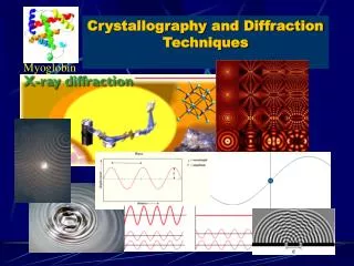
Up to now, we have only been concerned with determining sample chemistry quantitatively by EPMA and SEM • Chemistry is only half the story. How to tell polymorphs, like coesite from quartz, both are SiO2? • All minerals and most geologic and synthesized materials have a crystalline structure (except amorphous) • Diffraction uses either electron or x-ray sources to characterize the crystal structure • Bulk (XRD), micro (XRD, EBSD) or nano (TEM) diffraction techniques are used • Electron Back Scatter Diffraction (EBSD) is a relatively new technique for micro-diffraction by SEM Why do we care?
Coherent Scattering When x-rays or electrons interact with matter, the dominant effect is scattering. Considering x-rays and electrons as waves we deal with coherent scattering (rather than as particles, where we deal with incoherent scattering) For coherent scattering, x-rays and electrons are scattered with no loss of energy, and give rise to scattered radiation of the same wavelength This discussion (above) is taken mainly from Andre Guinier’s X-ray Cryallographic Technology, a 1952 translation of his 1945 classic Some of the following material is taken from Jim Connolly’s highly recommended UNM CXRD class notes: http://epswww.unm.edu/xrd/resources.htm
Constructive Interference The distance between atoms (dhkl) are on the same order of size as the wavelength of an x-ray Cu Ka =1.54Å) Interference phenomena is concentrated in directions related to the crystal lattice The intensity of the diffracted x-rays gives rise to peaks for each set of wave vectors which make up diffraction patterns The positions of the atoms in the material (the crystal lattice of the solid) and the wavelength of the x-rays determines the positions and intensities of the diffracted peaks. Another kind of scattering, incoherent (Compton), is easiest understood in terms of the particle nature of photons: the photon deviates from path and electron takes part of its energy. The scattered photon has lost energy (so has a longer wavelength), and there is no relationship between the phases of the two waves. There is no interference and of little significance here (though it is for XRF) and we will not consider it further.
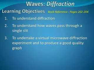
Diffraction Methods Laue method: a single crystal is held stationary in a beam of monochromatic x-ray radiation. The crystal diffracts the discrete values of l for which {hkl} planes exist of spacing dhkl and incidence angle q. To determine symmetry of a crystal. Rotating-crystal method: a single crystal is rotated about a fixed axis in a beam of monchromatic x-rays. The variation in q brings different atomic planes into position for reflection. Powder (Debye-Scherrer-Hull) method: a finely powdered sample is placed in a holder in a monochromatic x-ray beam, with the angle q gradually changing due synchronous movement of holder and detector. Assuming random orientation of the tiny crystallites, there will be diffraction off of different {hkl} planes at specific angles.
Intensity Diffraction, or coherent scattering Gas Intensity Diffraction angle 2q Liquid Amorphous Diffraction angle 2q Intensity Crystal Diffraction angle 2q
q q Scattered x-ray l Incident x-ray l Bragg’s Law dhkl
0, 0, 0 b* 010 020 030 040 a a* 100 110 120 130 Real space unit cell vs. reciprocal lattice b
Ewald Sphere of Reflection / Diffraction Crystal Real space Reciprocal lattice 2dhkl sinθ = λ
k, k’ – incoming wave vectors g – reciprocal lattice vector De Broglie relationship |k| = λ = p = hk Ewald Sphere Defines all possible g’s and k’s consistent with a particular relative orientation of the reciprocal lattice and k Ewald Sphere 1 h λ |p|
What does a powder really mean? Single Oriented Random
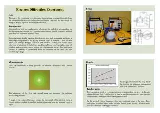
Powder X-ray Diffractometer LN Dewar X-ray tube Specimen Detector X-ray Diffractometer Controller and Data Collection Detector (Moving) 2θ θ (Fixed) θ HV X-ray tube (Moving) Crystal
S. W. Bailey XRD Laboratory A353 Weeks
Crystallographic structural analysis and unit-cell calculations • Quantitative determination of amounts of different phases (in multi-phase mixture) by peak-ratio calculations • Quantitative determination of phases by whole-pattern (Rietveld) refinement • Determination of crystallite size from peak broadening • Determination of crystallite shape from peak symmetry • Study of thermal expansion by using in-situ heating stage. XRD Applications
Ewald Sphere 18x larger X-ray diffraction EBSD CuKα x-ray λ=1.5418 Å e- (20 kV) λ=0.0859 Å |k| = = 0.65 Å-1|k| = = 11.64 Å-1 1 1 λ λ
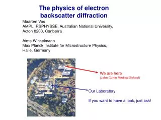
EBSD The sample is tilted steeply (55-70°) which enhances the number of BSEs able to undergo diffraction and escape the surface The HV electrons are scattered by the electrons of the atoms in the upper ~40 nm of the sample, scattering from electrons in {hkl} planes Kossel cones are the set of wave vectors for a given {hkl} and intersect with a phosphor screen forming Kikuchi patterns • The Kikuchi pattern provides information about the crystal structure: • Point symmetry of the crystal lattice • Width and intensity of bands are related to dhkl and the unit volume • Angles between bands are related to the angles between {hkl} planes
EBSD Specimen preparation is important: crystalline surface is the key! The surface layer of most samples is damaged from mechanical polishing by diamond grit/paste The damaged layer is removed by polishing with either colloidal silica or alumina (which also produces a chemical etch) Since the interaction volume is within the upper ~40 nm, EBSD analysis is done in VP-SEM and any conductive coating must be very very thin (~10Å carbon).
Shoji Nishikawa and Seishi KikuchiThe Diffraction of Cathode Rays by Calcite.Proc. Imperial Academy (of Japan) 4 (1928) 475-477 L-R: Yoshio Nishina, Seishi Kikuchi, Niels Bohr, laboratory in Japan.1937. Nishina Memorial Foundation, courtesy AIP Emilio Segre Visual Archives
Kikuchi bands: a 2-D pattern with 3-D information
EBSD Prior et al. (1999) American Mineralogist: 84, 1741-1759.
EBSD Prior et al. (1999) American Mineralogist: 84, 1741-1759.
Orientation Contrast Imaging • The upper two diodes detect backscattered electrons (BSE imaging) • Intensity varies with mean atomic number (Z) and is proportional to Z1.7 • The lower two diodes detect forescattered electrons (OC imaging) • Intensity varies due to differences in crystal orientation >> Z www.oxford-instruments.com/products/microanalysis/ebsd
Orientation Contrast Imaging • The control of the lattice on the variation in BSE intensity with exit beam trajectory is known as channeling-out (and diffracted beam) • The control of the lattice on the variation in BSE intensity with incident beam trajectory is known as channeling-in Prior et al. (1999) American Mineralogist: 84, 1741-1759.
Some References Prior, D.J. et al. (1999) The application of electron backscatter diffraction and orientation contrast imaging in the SEM to textural problems in rocks. American Mineralogist: 84, 1741-1759. Introduction to X-Ray Powder Diffraction, by Jim Connolly (notes for U NM EPS400-002, http://epswww.unm.edu/xrd/resources.htm) X-Ray Crystallographic Technology by Andre Guinier (English Translation, 1952) Modern Powder Diffraction by D. L. Bish and J. E. Post (eds), Mineralogical Society of America Reviews in Mineralogy, Vol 20, 1989 Electron Backscatter Diffraction in Materials Science, Edited by Adam J. Schwartz, Mukul Kumar and Brent L. Adams, Kluwer/Plenum, 2000, ISBN 0-306-46487-X (25 articles) An Atlas of Electron Backscatter Diffraction Patterns by D. J. Dingley, K. Baba-Kishi, and V. Randle, 1994, Institute of Physics Publishing.