Download
1 / 1
10 likes | 97 Vues
LASER CARTRIDGE. #1 MIRROR. GAS FILLED PLASMA TUBE ELECTRODES. RF ELECTRONICS. BEAM WIDOW. BEAM DIAMETER. #3 MIRROR. #2 MIRROR. r. FOCUS LENS. z. W.

E N D
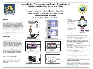
LASER CARTRIDGE #1 MIRROR GAS FILLED PLASMA TUBE ELECTRODES RF ELECTRONICS BEAM WIDOW BEAM DIAMETER #3 MIRROR #2 MIRROR r FOCUS LENS z W From the experimental data we have, when power equals to 60 Watts, the relation between gap and speed can be shown in Figure 3. We consider the data to be linear under the condition that the speed falls between 0.3 to 1.4 mm/s, so that the average data follows the linear equation in Figure 3. W is the width of the gap, V the speed of the laser. When speed equals to 0.3 mm/s, we can plot the result shown in Figure 4. Consider the data to be linear that the power falls between 36 to 60 Watts. The average data formed another linear equation in Figure 4. P is the laser power. Since we consider the two equations to be linear, a plane can be determined by the cross product of these two vectors, as shown in Figure 5. Now we rewrite (1) and (2) into the vector form as . Let , , then . Take Set E to be the initial condition. W = 0.425 mm, V = 0.3 mm/s, P = 60 Watts. The plane equation then be determined as (3). Rewrite equation (3) into (3*). The width of cutting for this acrylic material then was showed clearly. START Work pieces cut by laser Elements Inspecting bymachine vision Inspecting byCMM 1. Universal Laser Systems X-660 Laser Engraving and Cutting Systems 2. DVT 540 C series (color vision camera) 3. Yamaha RCX144 web-based controller 4. TESA Micro-Hite 3D CMM 5. Workpieces to be inspected 6. Remote Server Data frommachine vision Data fromCMM No Desired Results Yes Compare data Look for other methods Fig. 7: Flow Chart Fig. 3: The gap width versus laser output power measured by Machine Vision Fig. 4: The relation between gap width, speed, and power. Abstract The emergence of the laser and its subsequent development has presented the opportunity of increasing manufacturing capabilities, as well as to expand to new areas. Laser cutting of plastics offers advantages over conventional methods, such as no tool wear and contact force-induced material disintegration. However, the drawback in using the laser is the cut loss uncertainty and its tolerance controllability. In the current investigations, analytical heat conduction models are used to determine the extent of the cut loss induced errors. The results of the study of the effects of process parameters on the cut loss and quality performance achieved during laser cutting of plastic materials are presented. Key words: Laser cut loss, E-quality, E-machine vision, web-based quality control Laser Cutting Performance and Quality Evaluation via Web-Based Machine Vision and CMMPrincipal Investigators: Dr. Richard Chiou, Dr. Michael MaukResearch Assistants: Yueh-Ting Yang, Sweety AgarwalApplied Engineering TechnologyGoodwin College of Professional Studies Mathematical Relation Introduction The objective of this research is to determine the laser cutting quality in terms of kerf loss uncertainty and process parameters. A web-based quality control system via E-machine vision for inspecting part dimensions and tolerance is also described. Although the data can be gathered for statistics in short order, the assessment and interpretation of machine vision data is necessary; hence a CMM (coordinate-measuring machine) is used to validate the machine vision. Through the comparison of the data acquired from machine vision and CMM, the deviation of the machine vision can be estimated. Based on the data gathered by CMM, the power and the speed of laser cutting can also be analyzed. Thus, a model of laser cutting for plastic materials can be developed. The deviation of machine vision system is investigated, so that it can be appropriately applied in industrial areas. Fig. 2: Snapshot of the Application for E-Machine Vision. Fig. 1: The configuration for laser hole cutting. Fig. 3: Dependence of the gap width on the laser output power measured by CMM Fig. 4: Dependence of the gap width on the laser cutting speed measured by CMM Quality Control Methodology: Conclusion The main method is to evaluate the performance of laser cutting quality through web-based machine vision, to compare the data from machine vision and CMM, and to determine laser cutting quality after machine vision is calibrated for the laser cutting quality control. From the results, we can tell the measurement data from CMM are reliable and accurate. The rough cutting model was built through simple vector calculation. To predict the laser cutting quality of different material, this methodology could be further improved for the industrial area. However, the machine vision data need to be further investigated. From the technical support of the machine vision system developer, we know the accuracy of the machine vision system is about 1 mm at best. The width of the laser cutting falls between 0.3 to 0.45 mm. This will cause the unreliable error in the machine vision data. Higher pixel cameras and fine tuning are necessary to to improve the accuracy to as high as 0.01 mm.