Download

1 / 27
630 likes | 1.61k Vues
4-20mA Basics and 2-Wire vs. 3-Wire Transmitters. Material Created by Scott Hill Presented by Ian Williams May 23, 2011. Background. Prior to the 1950s, control of industrial sites was achieved with pneumatic systems 3 psi – 15 psi was used as the standard signal span 3 psi 0%

E N D
4-20mA Basics and 2-Wire vs. 3-Wire Transmitters Material Created by Scott Hill Presented by Ian Williams May 23, 2011
Background • Prior to the 1950s, control of industrial sites was achieved with pneumatic systems • 3 psi – 15 psi was used as the standard signal span • 3 psi 0% • 15 psi 100% • 3 psi used as a “live zero” • < 3 psi considered a fault condition or “dead zero” • The 4-20mA current loop was developed to emulate the old 3-15 psi pneumatic system
Typical 4-20mA Applications Report a process variable from a remote sensor to a control station. • Temperature, pressure, flow • 2-wire transmitter Transmit control signals from a control station out to a remote device. • Valve, actuator, heater • 3-wire transmitter
4-20mA Overview • 4mA represents 0% input level • Allows up to 4mA to power external input circuitry • 4mA zero level allows under-scale settings and fault detection • 20mA represents 100% input level • Provides sufficient current to power electromechanical devices • Over-scale can also be used to detect fault conditions
Why Use Current Transmitters? • Immunity to noise • Multiple unknown noise sources can exist between transmitter and receiver • Low impedance system prevents noise from impacting the accurate regulation of loop current • Long distance transmission • Signals must often travel distances > 1 mile • Impedance of long wires would severely attenuate a voltage signal • 4-20mA current loops are lossless, even over long distances • Kirchoff’s Current Law states that the current in a loop is equal at any point within the loop
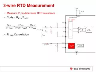
Why Is Signal Conditioning Required? • Linearity errors on most sensors creates an unacceptable error.
Transmitter Type Diagrams 2-Wire Transmitter 3-Wire Transmitter
2-Wire vs. 3-Wire Transmitter • Application-specific parameters determine which transmitter type should be used • Accessibility and location • System power requirements • Sensor input or voltage/current input
2-Wire vs. 3-Wire Transmitter • 2-Wire Transmitter (Loop powered) • Transmitter and sensor remotely located • Local power supply not practical • Input circuitry floats with respect to loop supply ground • 3-Wire Transmitter (Locally powered) • Transmitter located close to power supply • Input is referenced to power supply ground • Also known as a voltage-to-current converter
Implementation Of Current Transmitters • 2-Wire Transmitter • Submersible temperature sensor • Remote location prevents local power supply • Sends data back to control station • 3-Wire Transmitter • Sends control signal to element at remote location • Local power supply is available
2-Wire Typical Input Scaling • 4-20mA span is 16mA • XTR117 has current gain of 100 • Input span is 160µA • Offset current needed if input signal reaches zero
Typical 2-Wire Transmitter • IRET is not GND • Current Input • Current Output • Current gain set by R1 and R2 • Regulator and input circuitry floats at IRET potential
Internal Current Paths IINTotal = IIN + IOffset IR1 = IIN Total IR2 = IR1 * 99 ILOOP = IR1 + IR2
Equal Path Voltages Created VR1 = VR2
Calculating IRET Level VFLOAT = ILOOP * RL VFLOAT = ILOOP * RL VR2 = R2 * IR2 VR2 = R2 * IR2 V IRET = VFLOAT + VR2 V IRET = VFLOAT + VR2 V IRET = 5.495V V IRET = 1.099V
Effects of Grounding IRET IRET Floating IRET Grounded
Typical 3-Wire Transmitter • Input and Output are referenced to GND • Voltage Input • Current Output • Current gain set by VIN and RSET • Regulator referenced to GND