Download
1 / 38
380 likes | 537 Vues
Alignment of 3D Articulate Shapes. Articulated registration. Input: Two or more 3d point clouds (possibly with connectivity information) of an articulated object, possibly under different poses. Goal: Appropriately align all these point clouds together. Papers.

E N D
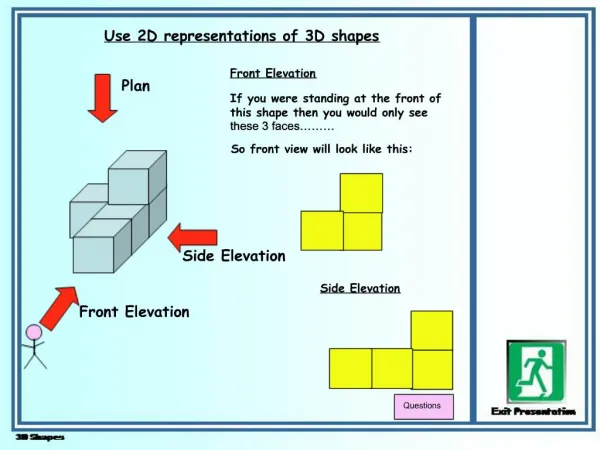
Articulated registration • Input: Two or more 3d point clouds (possibly with connectivity information) of an articulated object, possibly under different poses. • Goal: Appropriately align all these point clouds together
Papers • Automatic Registration for Articulated Shapes • Global Registration of Dynamic Range Scans for Articulated Model Reconstruction • KinectAvatar: Fully Automatic Body Capture Using a Single Kinect
Feature • Pre-compute per-vertex coordinate frames and feature descriptors (spin image) • Coordinate Frames (local coordinate system)
Spin Image • For a pair of points <p, x> => <> • Radially Symmetric
Spin Image • For a point p and a set of points
Spin Image • “Spin” – Radial Symmetry
Spin Image for articulated shape • Localized to small neighborhoods
Feature Matching: match spin images • mu is the median of the upper half of the measurements, ml is the median of the lower half of the measurements, fs= mu − ml
Motions sampling • for each correspondence candidate ( p,u) Where R and t are from the computed coordinate frames
Motion clustering • Mode finding on Lie Groups: mean shift • Mean shift [1,2] • Kernel Density Estimation • Move along the gradient of the kernel function [1] Y. Cheng, “Mean shift, mode seeking, and clustering,” IEEE TPAMI., vol. 17, no. 8, pp. 790 –799, aug 1995. [2] D. Comaniciu and P. Meer, “Mean shift: a robust approach toward feature space analysis,” IEEE TPAMI ,vol. 24, no. 5, pp. 603 –619, may 2002
Mean shift on Lie Groups • Six dimensional space: • The twist coordinate • Distance metric (used in the profile of mean shift kernel) • Original: • Simplified: O. Tuzel, R. Subbarao, and P. Meer, “Simultaneous multiple 3d motion estimation via mode finding on lie groups,” in Int. Conf. on Comput. Vision, vol. 1, oct. 2005, pp. 18 – 25 Vol. 1. 6
Assign candidate motions to all points • Treat each candidate motion as a label • Cast into a labeling problem, solved by graph cut: • argmin{ dataCost + smoothnessConstraint } • Data cost:
Assign candidate motions to all points • Treat each candidate motion as a label • Cast into a labeling problem, solved by graph cut: • argmin{ dataCost + smoothnessConstraint } • Smoothness constraint: preserve edge length
Assign candidate motions to all points • Treat each candidate motion as a label • Cast into a labeling problem, solved by graph cut: • argmin{ dataCost + smoothnessConstraint } • Symmetric smoothness constraint
Assign candidate motions to all points • Treat each candidate motion as a label • Cast into a labeling problem, solved by graph cut: • argmin{ dataCost + smoothnessConstraint } Why symmetric? The non-symmetric solution prefers to preserve the edge lengths
Results • See the paper • Note: provides segmentation simultaneously
Global Registration of Dynamic Range Scans for Articulated Model Reconstruction • Goal
Basic Idea • Given a set of range scans • Perform Pairwise Registration as initialization • Maintain a DSG (Dynamic Sample Graph, the final output) • Initially being the first frame (reference frame) • For each coming frame F, perform global registration: • Iterate: • Estimate transformations for each part of DSG to align with all frames up to F • Update segmentation of the DSG with the transformations • Update DSG with the new frame F
Algorithm Previous paper
Algorithm For all frames, “uniformly” sample the input point set as candidates [1] [1] MITCHELL, D. P. 1991. Spectrally optimal sampling for distribution ray tracing. ACM SIGGRAPH.
Algorithm Requires registration of DSG with the new frame
Register DSG with new frame • For each rigid part, uniformly blend all transformations of the points in this part.
Algorithm The number of points for this part is less than 5 or 10% of the part.
Global Registration • Iterate: • Estimate transformations for each part of DSG to align with all frames up so far • Update segmentation of the DSG with the transformations • Update DSG with the new frame F
Global registration • Part one: optimize transformations ICP-like Scheme: iterative Special part
Joints Estimation • On reference frame only • For all edges in DSG with end points crossing two rigid parts (with transformations Ta and Tb): • Average all end points to get initial estimation • Refine initial estimation by least square fitting:
Global registration • Part two: optimize weights • Similar to first paper: cast as labeling problem and use graph cut for optimization • Discard small regions Global registration done
Update DSG • Each time, start from an empty DSG • For each frame F • Include points from the candidates set of F if • Not overlapped based on distance and normal • Has a valid weight via interpolation • Weight interpolation (assign each point to a rigid part) • Why: • To add new points from the new frame • To reflect the update in transformations and label during global registration • How: • Compute distance to previous DSG, used as scores • Use the part form highest score, if it is significant compared to other scores
Algorithm MANSON, J., PETROVA, G., AND SCHAEFER, S. 2008. Streaming surface reconstruction using wavelets. Comput. Graph. Forum (Proceedings of SGP) 27, 5, 1411–1420.
Results • See Paper