IIR Filter Design: Basic Approaches
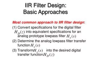
IIR Filter Design: Basic Approaches. Most common approach to IIR filter design : Convert specifications for the digital filter into equivalent specifications for an analog prototype lowpass filter Determine the analog lowpass filter transfer function

IIR Filter Design: Basic Approaches
E N D
Presentation Transcript
IIR Filter Design: Basic Approaches Most common approach to IIR filter design: • Convert specifications for the digital filter into equivalent specifications for an analog prototype lowpass filter • Determine the analog lowpass filter transfer function (3) Transform into the desired digital transfer function
Digital Filter Design: Basic Approaches • An analog transfer function to be denoted as where the subscript “a” specifically indicates the analog domain • A digital transfer function derived from will be denoted as
Digital Filter Design: Basic Approaches • Basic idea behind the conversion of into is to apply a mapping from the s-domain to the z-domain so that essential properties of the analog frequency response are preserved • Thus mapping function should be such that: • Imaginary axis in the s-plane be mapped onto the unit circle of the z-plane • A stable analog transfer function be mapped into a stable digital transfer function
analog digital s-plane z-plane S plane to Z plane mapping Preserve stability: Pole in the right half plan should map inside the circle in the z plan.
s-plane Euler Approximation Is the sampling interval
IIR Filter Design by Bilinear Transformation (1) Design Concept - s-plane to z-plane conversion • any mapping than maps stable region is s-plane (left half plane) • to stable region in z-plane (inside u.c) ? or bilinear transform! * Td inserted for convention may put to any convenient value for practical use.
IIR Digital Filter Design: Bilinear Transformation Method • Bilinear transformation • Above transformation maps a single point in the s-plane to a unique point in the z-plane and vice-versa • Relation between and is then given by * T inserted for convention may put to any convenient value for practical use.
Bilinear Transformation • Digital filter design consists of 4 steps: (1) Develop the specifications of HD(z) (2) Develop the specifications of (3) Design (4) Determine HD(z) by applying bilinear transformation to
* IIR Filter Design Procedure Given specification in digital domain Convert it into analog filter specification Design analog filter (Butterworth, Chebyshov, elliptic):H(s) Apply bilinear transform to get H(z) out of H(s) 1 2 3 4 3 2 4 1
Design a digital filter equivalent of a 2nd order Butterworth low-pass filter with a cut-off frequency fc = 100 Hz and a sampling frequency fs = 1000 samples/sec. • The normalised cut-off frequency of the digital filter is given by the following equation: • the equivalent analogue filter cut-off frequency ωac, The value of K is immaterial so let K = 1.
H(s) for a Butterworth filter is: • Hence the transfer function of the Butterworth filter becomes:
Next, convert the analogue filter into an equivalent digital filter by applying the bilinear z-transform. This is achieved by making a substitution for s in the transfer function. • The finite difference equation of the filter is found by inverting the transfer function
Direct form 2nd order http://ccrma.stanford.edu/~jos/filters/Direct_Form_II.html http://ccrma.stanford.edu/~jos/filters/Direct_Form_II.html
Direct realisation for a 2nd order Butterworth equivalent filter.
Matlab Bilinear • a=1; • b=[1, 1.141, 1]; • [c, d]=bilinear(a, b, 1000);