Download
1 / 11
200 likes | 1.37k Vues
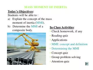
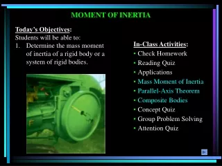
MASS MOMENT OF INERTIA (Section 17.1). Objectives : To determine the mass moment of inertia of a rigid body or a system of rigid bodies. APPLICATIONS.

E N D
MASS MOMENT OF INERTIA (Section 17.1) Objectives: To determine the mass moment of inertia of a rigid body or a system of rigid bodies.
APPLICATIONS The flywheel on the engine has a large mass moment of inertia about its axis of rotation. Once it is set into motion, it will be difficult to stop. Does the mass moment of inertia depend on the radius of the wheel? Its thickness? The crank undergoes rotation about a fixed axis that is not at its mass center. The crank develops a kinetic energy directly related to its mass moment of inertia. As the crank rotates, its kinetic energy is converted to potential energy and vice versa.
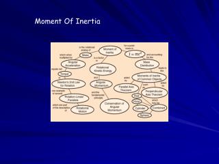
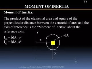
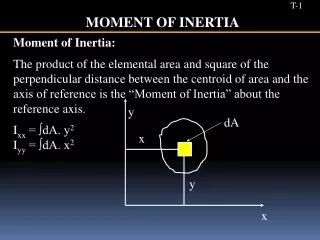
The mass moment of inertia is a measure of an object’s resistance to rotation: I = r2 dm = r2r dV r acts as the moment arm of the mass element and r is the density of the body. Thus, the value of I differs for each axis about which it is computed. m V MOMENT OF INERTIA In Section 17.1, the focus is on obtaining the mass moment of inertia via integration.
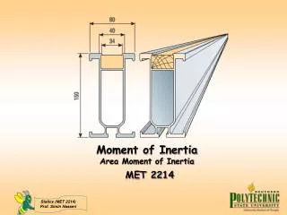
MOMENT OF INERTIA (continued) The figures show the mass moment of inertia formulations for two flat plate shapes commonly used when working with 3D bodies. The shapes are often used as the differential element being integrated over the entire body.
PROCEDURE FOR ANALYSIS Shell element • If a shell element having a height z, radius r = y, and thickness dy is chosen for integration, then the volume element is dV = (2πy)(z)dy Disk element If a disk element having a radius y and a thickness dz is chosen for integration, then the volume element is dV = (πy2)dz
1 1 rpx4 rp p(5) 8 ò ò = = = = Iy dy y dy 0 . 873 kg•m2 2 2 18 0 0 EXAMPLE 1 Given: The volume shown with r = 5 kg/m3. Find: The mass moment of inertia of this body about the y-axis. Solution: The moment of inertia of a disk about an axis perpendicular to its plane is I = 0.5 m r2. Thus: dIy = 0.5 (dm) x2 where dm = r dV = rpx2 dy.
PARALLEL-AXIS THEOREM The parallel axis theorem states: I = IG + md2 where IG = mass moment of inertia about the body’s mass center m = mass of the body d = perpendicular distance between the parallel axes
Radius of Gyration: has units of length and is a measure of the distribution of the body’s mass about the axis at which the moment of inertia is defined. I = m k2 or k = (I/m) PARALLEL-AXIS THEOREM (continued) Composite Bodies: If a body is constructed of a number of shapes, the mass moment of inertia of the body about any axis is the algebraic addition of all the mass moments of inertia, found about the same axis, of the different shapes.
Examples 17–18. The slender rods have a weight of 3 lb/ft. Determine the moment of inertia of the assembly about an axis perpendicular to the page and passing through point A.