Solar Car Data Collection System
Matt Boyden Rene Dupuis Ryan Lavallee. Solar Car Data Collection System. 2/12/08. Project Description.

Solar Car Data Collection System
E N D
Presentation Transcript
Matt Boyden Rene Dupuis Ryan Lavallee Solar Car Data Collection System 2/12/08
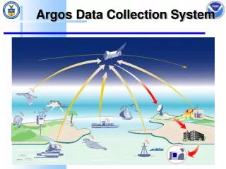
Rene Project Description Building miniature solar cars is a very common activity for teaching school-age kids about renewable energy. This was done this past summer at Vermont Tech and it is done all over the country. There are many solar car kits available for this type of activity. What does not exist is a way for teachers and students to collect data on the energy production and use - how much energy is used when the car is operated, how much is collected by the solar panel, how the power use changes over time when the car is operated, etc. All of this information would significantly enhance the learning experience for the students and the teacher. What is needed is a small, light data logging device specifically designed to interface with a typical educational solar car kit. The data collection system would need to collect time dependent data and then provide for the data to be downloaded and analyzed for learning.
Rene Project Requirements • Record data for a specific amount of time • Interface with a computer to easily output the information in a way that can be used for educational purposes • The product must be light enough and use little power so as not to change the performance of the car
Matt System Diagram Data Collection Micro- Controller Wheel Sensor Motor I Motor V Panel I Panel V
Matt System Diagram Data Output Micro- Controller Wheel Sensor Motor I Motor I Motor V Panel I Panel V
Matt Matt Circuit board layout HC12 programming, Data transmission to PC Responsibilities • Ryan • Data Retrieval • Excel VBA Programming • Rene • Wheel sensing, mechanical design • Sensor Selection
Matt Schedule
Matt Why the HC12? • The HC12 has Analog to Digital Converters • Has RS232 Chip Built into Module • 16kB Flash Memory for Data • Can be easily programmed using software that we already have • HC12 can be programmed on Docking Module then transferred to another Application
Matt HC12 Programming Requirements: • On Request: • Read Data from A2D Ports • Read Data from Wheel Sensor • Store Data • On Request or Timeout: • Stop Recording Data • On Request: • Transfer Data to Computer • Erase Memory
Matt Programming Flow Chart MAIN RECORD Start Read Data Initialization of Various Processes Store Data Start Record? Stop Record? Time Limit? Transmit? Delay
Matt Data Reading and Storage Process: • Data is read from A2D converters • One Reading is taken at a time • That Value is stored in Flash Memory • The next value is read • That is stored in the Flash address 2 above the previous value • Once all readings are taken the Microcontroller waits a specified amount of time and repeats the process Result: The data is stored one value at a time in Flash memory. By knowing the order in which the data was stored and the size of the groups (4 or 5 values) we can access the data and sort it in a usable fashion.
Matt Data Transmission • The data is sent one number at a time through an RS232 connection. We are currently using Teraterm to receive the data and capture it to a text file. • At the moment, we have transmitted a message and captured it to a text file. The next step is to read data from Flash and send it to the computer one number at a time. • Either before or after the data is transmitted it needs to be converted from the hex A2D reading to a voltage or current. • Since our A2D is set at 10 bits, each hex value is multiplied by 0.0049V to obtain a voltage. • 5V/1023 steps = 0.0049V/step • Current = Voltage/Resistor Value
Excel File Manipulation • Write Visual Basic software to manipulate .txt file in Excel • The program will provide the teacher with following data and there corresponding graphs • Velocity (ft/s) • Total Power Consumption (watts) • Voltage and Current plot for duration of race (V,A)
How Excel Program works • Visual Basic is used to program an Excel spreadsheet • Program references .txt file • Places .txt file using predefined rows • Excel is then programmed to make according calculations and produce graphs of all the data • The cells and graphs will have labels programmed for them so all results are easily identified by teacher and student
Simplify for Teacher • The goal is to give the teacher one file where s/he will be instructed to open only the excel file and run the macro
Steps For Teacher • Open Excel Sheet • Hit Tools->Macros->select our macro name • Watch Graphs pop up
Rene Current Sensor • Prefer Resistors • Cars have clip leads for motor • Easy to use a resistor • May have to amplify the voltage from the resistor if it is too low and then convert back to a Current
Current Sensor (option) • MAX471 set up to produce 0-1V corresponding to 0-1A output • Can operate with input voltage of 3-36V • R(out) = V(out) / I(load) *R(sense) = 1V / (1A * .500mA) = 2k ohms Rene
Hall Effect Sensor Applications • Applied 4 magnets and record 4 • data points per revolution • Had sensor positioned beside wheel • Applied 1 magnet and record • 1 data point per revolution • Have sensor positioned at a point • along front shaft (hanging down) Rene
Hall Effect Sensor • Allegro A3211 hall-effect switch • Pros • Range was good • Quick switch times • Cons • Too sensitive; picked up magnetic field no matter distance • Very small design • Mounting an issue Rene
Proximity Sensor • Used CherryMP201701 • Pros • Gave accurate results • Mounting more reasonable • More durable than Hall Effect • Cons • Limited Range • Long delay between switch times Rene
Tow-Behind Wheel • Measure number of revolutions during travel • Convert to RPM’s/Velocity • Attached behind car • Drag coefficient added Rene
Budget Rene
Rene Next Steps • Choose Battery • Run Independent of Docking Module • Transmit actual data through entire process
Ryan will answer any questions Questions?