Living on Water - Floating Structures in Singapore
Living on Water - Floating Structures in Singapore. Outline. Introduction &Objective Disadvantages of Land Reclamation Types of Floating Structures Advantages of Floating Structures Characteristics of Pontoon Floating System Case Study: The Float @ Marina Bay


Living on Water - Floating Structures in Singapore
E N D
Presentation Transcript
Outline • Introduction &Objective • Disadvantages of Land Reclamation • Types of Floating Structures • Advantages of Floating Structures • Characteristics of Pontoon Floating System • Case Study: The Float @ Marina Bay • Our Improvised Floating Structure • Advantages over existing system • Installation procedure
Introduction • The scarcity of land became a major problem in Singapore • Land usages undergo threat, due to the increase in population and modern urbanization • Singapore has to depend heavily on land reclamation, but it’s expensive
Disadvantages of Land Reclamation • Damage to Marine Life • Dumping sand • Building a wall around the new shoreline • Disrupt the habitat of marine life • High cost • Lack of resources (e.g. sand) • Singapore forced to buy sand • From Malaysia and Indonesia
Disadvantages of Land Reclamation (Cont’d) Flood threat from Singapore alleged The Straits Times March 21, 2002 JOHOR BARU - A Johor University academic has alleged Singapore's reclamation works on its islands in the north-east could turn settlements along several rivers in Johor into flood-prone areas.Prof Dr Ahmad Khairi Abdul Wahab, a coastal engineer, said settlements along Sungai Santi, Sungai Belungkor, Sungai Johor, Sungai Kim Kim and Sungai Leban could come under threat when Singapore's PulauTekong and PulauUbin double their size and halve the capacity of the Johor Straits. Singapore soil works 'hurt JB fishing'. The Straits Times July 9, 2003 KUALA LUMPUR - The reclamation issue has cropped up again, with BeritaHarian Malaysia saying Singapore's reclamation work on PulauTekongBesar and PulauTekong Kecil was affecting marine life habitats in Johor. Quoting a statement by local Umno politician MdLazimAtan, the newspaper said the reclamation work was also destroying coral at the mouth of the Johor river.
Objective • To find alternative methods to land reclamation • To improve on the assembly method of the existing floating system
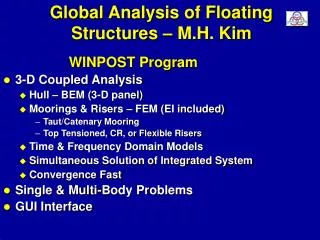
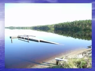
Types of Floating System • Floating Structure
Advantages of Floating System • Minimal disruption to marine eco-system • Cost effective • Faster construction time • Flexibility • Others
Characteristics of Pontoon Floating Systems • A very large pontoon floating structure • Mooring facility to keep the floating structure in place • An access bridge or floating road to get to the floating structure from shore • A breakwater for reducing wave forces impacting the floating structure.
Types of Mooring System • The chain method • Ties one end to the floating pontoon and the other end to seabed • The tension leg method • Similar to chain method • The Pier/ Quay method • makes use of existing pier/quay to connect the pontoon • The dolphin method
Case Study: The Float at Marina Bay
The Float at Marina Bay • Iconic structure • First and biggest floating system • Usable space of 120m x 83m on the water • Designed to carry a heavy load • Act as a temporary location for holding events (E.g. National Day celebration) • Largest floating stage in the world for performances on water
The Float at Marina Bay Methods of Assembly
Methods of Assembly • Pontoon System • Pontoon Connection System • Access Deck • Breakwater System • Detachable Dolphin Mooring System
1. Pontoon System • 15 identical steel pontoons of dimensions 40m x 16.6m x 1.2m each • 5 by 3 layout, to form the ultimate 120m x 83m floating platform
1. Pontoon System • Made of welded mild steel construction • Based on considerations of the shallow water depth and the need to carry heavy live loads • Shallow water limits the platform depth to a height of approximate 1.2m • Tests such as the Static Bending test and Hydro elastic Analysis were carried out
Static Bending Analysis 1. Pontoon System • To determine the stress distributions and deflection ofthe platform as well as the maximum loads at the connecting system • Stresses are checked to ensure they meet strength requirements • Vertical deflections are checked against serviceability requirements
1. Pontoon System Hydro Elastic Analysis • Carried out to estimate the structure and connector loads when the floating system is exposed to wave movements
Pontoon Connection System • Comprises 20 nos. of 4m x 4m diamond-shaped corner connectors and 80 nos. of side connectors to join the pontoons together Corner Connectors (Total Nos: 20) Side Connectors (Total Nos: 80)
Pontoon Connection System (Cont’d) • Corner connector’s hollow edge is slipped into the tapered wedge of the pontoons • Comprises 5 side connectors along the longer mating edges and 2 of such along the shorter edge • Locked by detachable locking pins engaging the coupling members Corner Connector Side Connector
Methods of Assembly • Pontoon System • Pontoon Connection System • Access Deck • Breakwater System • Detachable Dolphin Mooring System
2. Access Deck • Comes in the form of three access bridges ( 8m to 10m wide) • Connect the floating platform to shore for human and vehicular access • Designed with adequate strength, deflection and vibration • Considerations like structural soundness and sufficient width to ensure smooth traffic flow will be put into the design
Methods of Assembly • Pontoon System • Pontoon Connection System • Access Deck • Breakwater System • Detachable Dolphin Mooring System
3. Break Water System • There is a tidal variation of about 3m to 4m in the site area before the completion of the Marina barrage • Such risk will not become a problem anymore after Marina barrage has been built • Its presence isolates the Marina Bay as a reservoir, forming a kind of breakwater system for the floating platform • Surface water become as calm as a lake, with minimal tidal movements
Methods of Assembly • Pontoon System • Pontoon Connection System • Access Deck • Breakwater System • Detachable Dolphin Mooring System
4. Detachable Dolphin Mooring System • Comprises caissons or jacket-frames with piles and fenders • More effective in restraining horizontal movement • Roller fenders is the key factors to the success or failureof the whole system Roller fenders connection
4. Detachable Dolphin Mooring System (cont’d) • The mooring columns consist of 2 section piles: • Vertical upper pile column • Being detachable above sea bed • Vertical lower pile column • Fixed and rammed 16-20mm into the seabed • Leaving a protrusion of about 1/2m above
Advantages of Detachable Dolphin Method • Involves simple installation process • Kept the floating platform in position • Minimise sea space usage • The components are detachable & reusable • Stable connection to the seabed • Allows disconnection when required so as to be transported away • It has a speedy construction
Disadvantages of Detachable Dolphin Method • Over design of system • Bolt and nuts connection of dolphin columns • Damaged by rollers fenders
Disadvantages of Detachable Dolphin Method • Over design of system • Being the first & only marina floating system • Additional tests & materials used contribute to the high construction cost. • Over design features includes: • The additional depth of the pontoons • The extra thickness of dolphin columns • The limitation to just 15 numbers of pontoons for the entire floating system
Disadvantages of Detachable Dolphin Method • Over design of system • Bolt and nuts connection of dolphin columns • Damaged by rollers fenders
Disadvantages of Detachable Dolphin Method • Bolt and nuts connection of dolphin columns • Bolts and nuts are meant for connection of the two sectional piles • It’s located underwater for long period of time • Subjected to risks of facing corrosion • Break off over time
Bolt and Nuts Connection of Dolphin Columns Sea level Sea bed Bolt and nuts connection
Disadvantages of Detachable Dolphin Method • Over design of system • Bolt and nuts connection of dolphin columns • Damaged by rollers fenders
Disadvantagesof Detachable Dolphin Method • Damaged by rollers fenders: • Failure in the connection between roller fenders and dolphin columns • The roller fenders allows pontoon to slide up and down the dolphin columns
Disadvantagesof Detachable Dolphin Method • Damaged by rollers fenders (cont’d): • The vertical movement along that specific area, causes wear and tear (shown in picture)
Improvised Floating System • Focus will be placed into improving the dolphin mooring system • New system aims to reduce the construction and material costs • To improve on the safety and potential risk areas
Proposed Improvements • Decrease of depth of pontoon height • Spin fins piles for driving into seabed • Protection steel plate at rollers fenders • Recessed connection between dolphin section piles
1. Decrease of Depth of Pontoon Height Current system in place at Marina floating structure • Designed with additional safety factors • Existing height of each floating pontoon is approximate 1.2m high • With the 15 pontoons in place of 40m x 16.6m x 1.2m high each, the design is in excess of the initial planned load capacity • View was supported by Prof. C. M. Wang, who also felt that the pontoon was slightly over-designed
1. Decrease of Depth of Pontoon Height (Cont’d) Proposed system • To decrease the depth of each pontoons from 1.2m high to 1.1m high • The reduction will slightly decrease the load carrying capacity • Despite being lower, is still capable of sustaining the maximum load limit • Reduction in materials usage & construction cost • Save up to 1000m3 of steel
Proposed Improvements • Decrease of depth of pontoon height • Spin fins piles for driving into seabed • Protection steel plate at rollers fenders • Recessed connection between dolphin section piles
2. Spin Fins Piles for Driving into Seabed • Consist of a pile equipped with angled plated fins • Piles are rotated and driven into the seabed to achieve pile capacities far in excess of conventional piles • The advantages of using the spin fin piles: • provide sufficient strength • reduce the length of the piles • additional fins provide additional support • length of the piles can be reduced by as much as 50% • Idea adopted from PND Engineers Inc.
Spin Fin Tips Pile head Isometric View of Spin Fin and Pile Head Connection 2. Spin Fins Piles for Driving into Seabed (Cont’d) Example of how the spin fin piles will look like in actual implementation: Pile head Spin Fin Tips Side View Connection of Spin Fin and Pile Head
2. Spin Fins Piles for Driving into Seabed (Cont’d) Isometric view of Connection between Spin Fin and Pile Head and Pile Bottom view of Connection between Spin Fin and Pile Head
Proposed Improvements • Decrease of depth of pontoon height • Spin fins piles for driving into seabed • Protection steel plate at rollers fenders • Recessed connection between dolphin section piles
3. Protection Steel Plate at Rollers Fenders • One of the risks was the wear and tear damage caused to the connection between the roller fenders and the dolphin columns • To counter the risk we proposed to install steel plates to the area where roller fenders are in contact with the dolphin columns • Proposed size of the steel plates shall be 300 x 300 x 10mm thick
3. Protection Steel Plate at Rollers Fenders (Cont’d) Example of how the add-on of steel plates will look like in actual implementation Rollers Dolphin Fenders Metal Plate Isometric View of Dolphin rollers & fenders Detail view of Dolphin rollers & fenders with a add on metal plate
3. Protection Steel Plate at Rollers Fenders (Cont’d) Top View of Dolphin rollers & fenders Bottom View of Dolphin rollers & fenders