Download
1 / 38
420 likes | 606 Vues
DEVICES AND COMMUNICATION BUSES FOR DEVICES NETWORK. Bus Communication for networking. Each specific I/O device may be connected to other using specific interfaces, for example, with I/O device for example, LCD controller, keyboard controller and print controller.

E N D
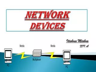
Bus Communication for networking • Each specific I/O device may be connected to other using specific interfaces, for example, with I/O device for example, LCD controller, keyboard controller and print controller. • Bus communication simplifies the number of connections and provides a common way (protocol) of connecting different or same type of I/O devices
IO Bus • Any device that is compatible with a system's I/O bus can be added to the system (assuming an appropriate device driver program is available), and a device that is compatible with a particular I/O bus can be integrated into any system that uses that type of bus. • I/O devices communicate with the processor through an I/O bus, which is separate from the memory bus that the processor uses to communicate with the memory system.
Embedded systems Networking • Embedded systems connected internally on same IC or systems at very short, short and long distances can be networked using a type of the I/O buses- CAN, I2C, USB, PCI, …
IO Bus for Networking vs. direct connections • Use of I/O bus, as opposed to direct connections between the processor and each I/O device, very flexible, allowing a system to support many different I/O devices depending on the needs of its users and allowing users to change the I/O devices that are attached to a system as their needs change.
Main disadvantage of an I/O bus • A bus has a fixed bandwidth that must be shared by all of the devices on the bus. • Even worse, electrical constraints (wire length and transmission line effects) cause buses to have less bandwidth than using the same number of wires to connect just two devices. • Essentially, there is a trade-off between interface simplicity and bandwidth. Example • A bus has bandwidth of 2 Mb/s (can be used to transfer 2 Mb data in one s. • If 10 devices are connected, the 2 Mb/s is shared between the networked systems
Serial Bus • A serial bus has very few lines and the number of lines as per the protocol. • A wide range of I/O devices without having to implement a specific interface for each I/O device. When the I/O devices in the distributed embedded systems are networked at long distances of 25 cm and above, all can communicate through a common serial bus.
Internet or intranet • Using Internet or intranet, a computer or controller or embedded system IO device interface and globally network with computers and a wide range of devices in the systems Parallel Bus • Using a parallel I/O bus allows a computer or controller or embedded system to interface with number of internal systems at very short distances without having to implement a specific interface for each I/O device.
Short distances Wireless Bus protocol • Up to 100 m using wireless personal area network (WPAN) • WPAN protocol without having to implement a specific wireless interface for each I/O device • Allows a handheld computer or controller or embedded system I/O device to interface and network with number of handheld system I/O devices of other handheld
Interconnecting number of device circuits • Assume flash memory, touch screen, ICs for measuring temperatures and ICs for measuring pressures at a number of processes in a plant. • ICs mutually network through a common synchronous serial bus I2C • An 'Inter Integrated Circuit' (I2C) bus, a popular bus for these circuits.
Synchronous Serial Bus Communication for n/wing • Each specific I/O synchronous serial device may be connected to other using specific interfaces, for example, with I/O device using I2C controller • I2C Bus communication− use of only simplifies the number of connections and provides a common way (protocol) of connecting different or same type of I/O devices using synchronous serial communication
IO I2C Bus • Any device that is compatible with a I2C bus can be added to the system (assuming an appropriate device driver program is available), and a I2C device can be integrated into any system that uses that I2C bus.
Originally developed at Philips Semiconductors • Synchronous Serial Communication 400 kbps up to 2 m and 100 kbps for longer distances • Three I2C standards 1. Industrial 100 kbps I2C, 2. 100 kbps SM I2C, 3. 400 kbps I2C
I2C Bus • The Bus has two lines that carry its signals— one line is for the clock and one is for bi-directional data. • There is a standard protocol for the I2C bus. Device Addresses and Master in the I2C bus • Each device has a 7-bit address using which the data transfers take place. • Master can address 127 other slaves at an instance. • Master has at a processing element functioning as bus controller or a microcontroller with I2C (Inter Integrated Circuit) bus interface circuit.
Slaves and Masters in the I2C bus • Each slave can also optionally has I2C (Inter Integrated Circuit) bus controller and processing element. • Number of masters can be connected on the bus. • However, at an instance, master is one, which initiates a data transfer on SDA (serial data) line and which transmits the SCL (serial clock) pulses. From master, a data frame has fields beginning from start bit.
Synchronous Serial Bus Fields and its length • First field of 1 bit─ Start bit similar to one in an UART • Second field of 7 bits─ address field. It defines the slave address, which is being sent the data frame (of many bytes) by the master • Third field of 1 control bit─ defines whether a read or write cycle is in progress • Fourth field of 1 control bit─ defines whether is the present data is an acknowledgment (from slave)
Synchronous Serial Bus Fields and its length • Fifth field of 8 bits─ I2C device data byte • Sixth field of 1-bit - bit NACK (negative acknowledgement) from the receiver. If active then acknowledgment after a transfer is not needed from the slave, else acknowledgement is expected from the slave • Seventh field of 1 bit ─ stop bit like in an UART
Disadvantage of I2C bus • Time taken by algorithm in the hardware that analyzes the bits through I2C in case the slave hardware does not provide for the hardware that supports it. • Certain ICs support the protocol and certain do not. • Open collector drivers at the master need a pull-up resistance of 2.2 K on each line.
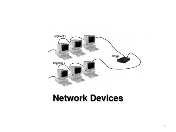
Serial Communication DistributedControl Area Network (CAN) Bus Distributed Control Area Network example - a network of embedded systems in automobile
CAN Serial Bus Communication forNetworking • CAN-bus line usually interconnects to a CAN controller between line and host at the node. It gives the input and gets output between the physical and data link layers at the host node. • The CAN controller has a BIU (bus interface unit consisting of buffer and driver), protocol controller, status-cum-control registers, receiver-buffer and message objects. These units connect the host node through the host interface circuit
Three standards: • 33 kbps CAN, • 110 kbps Fault Tolerant CAN, • 1 Mbps High Speed CAN CAN protocol There is a CAN controller between the CAN line and the host node. • CAN controller ─BIU (Bus Interface Unit) consisting of a buffer and driver • Method for arbitration─ CSMA/AMP (Carrier Sense Multiple Access with Arbitration on Message Priority basis)
Each Distributed Node Uses: • Twisted Pair Connection up to 40 m – for bi-directional data • Line, which pulls to Logic 1 through a resistor between the line and + 4.5V to +12V. : • Line Idle state Logic 1 (Recessive state) • Uses a buffer gate between an input pin and the CAN line • Detects Input Presence at the CAN line pulled down to dominant (active) state logic 0 (ground ~ 0V) by a sender to the CAN line • Uses a current driver between the output pin and CAN line and pulls line down to dominant (active) state logic 0 (ground ~ 0V) when sending to the CAN line
Protocol defined start bit followed bysix fields of frame bits • Data frame starts after first detecting that dominant state is not present at the CAN line with logic 1 (R state) to 0 (D state transition) for one serial bit interval • After start bit, six fields starting from arbitration field and ends with seven logic 0s end-field • 3-bit minimum inter frame gap before next start bit (R→ D transition) occurs
Protocol defined First field in frame bits • First field of 12 bits ─'arbitration field. • 11-bit destination address and RTR bit (Remote Transmission Request) • Destination device address specified in an 11-bit sub-field and whether the data byte being sent is a data for the device or a request to the device in 1-bit sub-field. • Maximum 211 devices can connect a CAN controller in case of 11-bit address field standard
11-bit address standard CAN • Identifies the device to which data is being sent or request is being made. • When RTR bit is at '1', it means this packet is for the device at destination address. If this bit is at '0' (dominant state) it means, this packet is a request for the data from the device.
Protocol defined frame bits Second field • Second field of 6 bits─ control field. The first bit is for the identifier’s extension. • The second bit is always '1'. • The last 4 bits specify code for data length Protocol defined frame bits Third field • Third field of 0 to 64 bits─ Its length depends on the data length code in the control field.
Protocol defined frame bits Fourth field • Fourth field (third if data field has no bit present) of 16 bits─ CRC (Cyclic Redundancy Check) bits. • The receiver node uses it to detect the errors, if any, during the transmission
Protocol defined frame bits Fifth field • Fifth field of 2 bits─ First bit 'ACK slot‘ • ACK = '1' and receiver sends back '0' in this slot when the receiver detects an error in the reception. • Sender after sensing '0' in the ACK slot, generally retransmits the data frame. • Second bit 'ACK delimiter' bit. It signals the end of ACK field. • If the transmitting node does not receive any acknowledgement of data frame within a specified time slot, it should retransmit.
Protocol defined frame bits Sixth field • Sixth field of 7-bits ─ end- of- theframe specification and has seven '0's.