Download
1 / 25
250 likes | 270 Vues
This report discusses the essential requirement of precise angle measurement for accurate luminosity measurement using the LAT Calorimeter. It explores different geometry setups, such as the standard setup, flat LAT, and stripped LAT, and their improvements in angle resolution. Challenges in lumi measurement and detector alignment are also addressed.

E N D
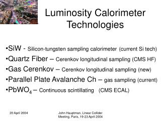
LAT calorimeter options L.Suszycki, Cracow Forward Calorimetry WG, Amsterdam, 31 March 2003
LAT luminosity measurement Essential for precise luminosity measurement is a precise angle measurement of the Bhabha scattered electrons. L/L = 10-4needsmin = 1.4 rad The standard (TDR) setup enables only 0.2 – 0.3 mrad accuracy with the price of 13440 channels. We try • The standard setup improvements and to consider alternative geometry setups: • Flat LAT • Stripped LAT Amsterdam 31. March ‚03 L.Suszycki, Cracow
Improvements comparing to the Prague results: Silicon sensors arranged in planes Non-projective cylinders of equal height Angle reconstruction using All sensors : =~0.9 mrad Every 4th sensor : =~1.1 mrad Every 10th sensor : =~1.5 mrad Improved LAT geometry It is resonable to apply fine segmentation to a fraction of cylinders only Amsterdam 31. March ‚03 L.Suszycki, Cracow
Leackage makes precision Lumi hard Amsterdam 31. March ‚03 Achim Stahl DESY Zeuthen
All cylinders start at z=136 cm 7, 14, 18 or 56 cylinders assumed Conical projective geometry is kept (TDR) Sergey Kananov, Tel Aviv Angle reconstruction Flat LAT geometry Gain in angle resolution = 2.5at price of increasing of #channels of factor 56/14=4! Amsterdam 31. March ‚03 L.Suszycki, Cracow
Only rings near the shower maximum at ring #8 are significant for theta reconstruction: 1, 3, 5, 7, 10, 16 or 20 „active” rings One can reach better angular resolution with similar #channels: Uniform: 14 x 30 x 24 = 10080=> 0.18 mrad 5 rings 2-fold granulated: 11760=> 0.13 mrad 5 rings 4-fold granulated: 15120=> 0.09 mrad Flat LAT shower maximum methodSergey Kananov, Tel Aviv Amsterdam 31. March ‚03 L.Suszycki, Cracow
Stripped LAT geometryBogdan Pawlik, Cracow Silicon 1mm strips arranged in20 cones to read r and z x 256 strips+20 cones to read φ x 72 strips =>6560 channls in total = gen - rec (radians) vs. strip layer („cylinder”) = ~0.9mrad at 9st layer Amsterdam 31. March ‚03 L.Suszycki, Cracow
LAT conclusions • Preliminary results on alternative LAT geometry are obtained • Much more MC work is necessary to get closer to the required acurracy of the angle measurement • Still awaiting for the Flat Mask decision Amsterdam 31. March ‚03 L.Suszycki, Cracow
Challenges in Lumi Measurement Some studies of sensitivity to systematic uncertainties Amsterdam 31. March ‚03 Achim Stahl DESY Zeuthen
Method BHLUMI (Ver. 4.04) No Detector Simulation Generate an event calculate coordinates on calorimeter apply systematic shifts recalculate coordinates apply selection cuts count events Lumi E+, E- > 0.8 Ebeam Acol < 11.5o 30 mrad < θ+ < 75 mrad 30 mrad < θ-< 75 mrad Amsterdam 31. March ‚03 Achim Stahl DESY Zeuthen
Offset of Beams from Axis Lin. Coeff. ≈ 0 Quadratic Coeff.: Δoffset < 200 μm Amsterdam 31. March ‚03 Achim Stahl DESY Zeuthen
Inner Radius of Calorimeter : Longitudinal Distance of Calorimeters : ΔL/L ≈ 1.3 10-4/ μm ΔL/L ≈ -0.0033 / mm z+ - z- < 60 μm Amsterdam 31. March ‚03 Achim Stahl DESY Zeuthen
Conclusions To achieve ΔL / L ≈ 10-4: Beam Offsets: < 200 μm Inner Radius of Cal < 0.75 μm Distance of Cals < 60 μm Center-of-Mass Energy: process dependent but that‘s not all yet Amsterdam 31. March ‚03 Achim Stahl DESY Zeuthen
LAT detector alignment Wojciech Wierba Institute of Nuclear Physics Cracow Poland Jerzy Zachorowski M. Smoluchowski Institute of Physics Jagiellonian University Photonics Group Cracow Poland Amsterdam 31. March ‚03 Wojciech Wierba Cracow, Poland
The luminosity measurement requires precision alignment of the LAT detectors and stable, precision placement in reference to the interaction point. The beam pipe becomes as a suitable reference because the Beam Position Monitors are mounted inside the vacuum pipe. This allows us to correct the real LAT detectors position in respect to the beam position. There are four tasks: Measurement of the beam pipe dimensions in the lab. Radial metrology and mechanical design of the LAT detectors. Initial alignment of the LAT detectors in the forward region. On line system to measure displacement of the LAT detectors. LAT alignment Amsterdam 31. March ‚03 Wojciech Wierba Cracow, Poland
On line system to measure displacement of the LAT detectors • The Photonic sensor for the z (along the beam) distance measurement: • Small probe head, just end of the ~3mm fiber. • Lightweight probe to be attached to the flange of the beam pipe. • All electronics and laser can be placed outside the TESLA detector. • Only fibers have to be feed near the LAT detector. • Continuous laser beam is not necessary i.e. power fault, laser change/repair. Amsterdam 31. March ‚03 Wojciech Wierba Cracow, Poland
On line system to measure displacement of the LAT detectors • Fine pixel CCD sensor to measure x, y and position : The CCD detector should be glued to the rear face of the calorimeter. The laser beam can be distributed via optical fiber. The laser spot will be formed by collimator or optics. • Advantages : • Small and lightweight collimator/optics to be attached to the flange of the beam pipe. • Laser can be placed outside the TESLA detector. • Continuous laser beam is not necessary i.e. power fault, laser change/repair. • Only some cables and fiber have to be feed near the LAT detector. • Problems : • Radiation hardness of the CCD sensor and electronics. The CCD will be placed between rear side of the LAT calorimeter and tungsten shield and probably the radiation dose will be not so high. • Background from the particles. The position measurement can be done in the time slot between trains when beams are not present. The speed of the CCD sensor is sufficient to do that. Amsterdam 31. March ‚03 Wojciech Wierba Cracow, Poland
First results from silicon and diamond sensors K. Afanasiev1, I. Emeliantchik1, E. Kouznetsova2, W. Lohmann2, W. Lange2 1NC PHEP, Minsk 2DESY Zeuthen
Sr ADC delay in PA diamond discr gate Test Set Up or Amsterdam 31. March ‚03 E. Kouznetsova DESY Zeuthen
Signals from 90Sr – silicon and diamond : Si (mip) Diamond (whole b-spectra) Diamond (noise) Diamond Amsterdam 31. March ‚03 E. Kouznetsova DESY Zeuthen
Problems and further steps : • Noise level is not optimal for signal/noise separation (ENC ≈700 e) • Possible solutions : • Noise optimization of the existing preamplifier • Switch to Amptek A250 (noise expected ≤ 350 e) • New trigger scintillator matching the size of the sensor • New diamond samples : • Fraunhofer Institute (Freiburg) : (12 x 12 mm) 300 and 200 mm Different surface treatments • Prokhorov Institute (Moscow) - Dubna group Amsterdam 31. March ‚03 E. Kouznetsova DESY Zeuthen
New Design of the Mask • For L* = 3 m performance of the mask calorimeters is doubtful • For larger L* things look easier • Question: How much L* do we need? Achim Stahl DESY Zeuthen
Fake Photons Leackage makes precision Lumi hard Too close to beamstrahlung Amsterdam 31. March ‚03 Achim Stahl DESY Zeuthen
Advantages • Luminosity: More likely to achieve 0.01 % • No fakes can scatter from mask into ECal • Vacuum much better, large orfice, bellow, valve • Space for electronics available • Better separation of outer Cal from beamstrahlung (5cm -> 8cm) • Hermetic to 3.9 mrad (was 5.5 with gaps) • Shintake monitor taken into account L* approx. 4 meters Amsterdam 31. March ‚03 Achim Stahl DESY Zeuthen