Download
1 / 67
670 likes | 758 Vues
Understanding Neutron Radiography Reading VIII-Defence Laboratory-A

E N D
Understanding Neutron R adiography R eading VIII– Defence Laboratory, J odhpur-342 001 My ASNT Level III, Pre-Exam Preparatory Self Study Notes 30 August 2015 Charlie Chong/ Fion Zhang
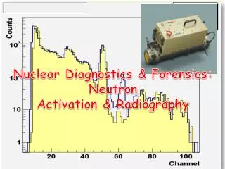
Military Applications Charlie Chong/ Fion Zhang
Military Applications Charlie Chong/ Fion Zhang
Military Applications Charlie Chong/ Fion Zhang
Military Applications Charlie Chong/ Fion Zhang
The Magical Book of Neutron Radiography Charlie Chong/ Fion Zhang
数字签名者:Fion Zhang DN:cn=Fion Zhang, o=Technical, ou=Academic, email=fion_zhang@ qq.com, c=CN 日期:2016.08.07 16:23:23 +08'00' Charlie Chong/ Fion Zhang
ASNT Certification Guide NDT Level III / PdM Level III NR - Neutron Radiographic Testing Length: 4 hours Questions: 135 1. Principles/Theory • Nature of penetrating radiation • Interaction between penetrating radiation and matter • Neutron radiography imaging • Radiometry 2. Equipment/Materials • Sources of neutrons • Radiation detectors • Non-imaging devices Charlie Chong/ Fion Zhang
• Electron emission radiography • Micro-radiography 3. Techniques/Calibrations • Blocking and filtering • Multifilm technique • Laminography (tomography) • Enlargement and projection • Stereoradiography • Control of diffraction effects • Panoramic exposures • Triangulation methods • Gaging • Autoradiography • Flash Radiography • Real time imaging • Image analysis techniques • In-motion radiography • Fluoroscopy Charlie Chong/ Fion Zhang
4. Interpretation/Evaluation • Image-object relationships • Material considerations • Codes, standards, and specifications 5. Procedures • Imaging considerations • Film processing • Viewing of radiographs • Judging radiographic quality 6. Safety and Health • Exposure hazards • Methods of controlling radiation exposure • Operation and emergency procedures Reference Catalog Number NDT Handbook, Third Edition: Volume 4, Radiographic Testing 144 ASM Handbook Vol. 17, NDE and QC 105 Charlie Chong/ Fion Zhang
Fion Zhang at Shanghai 30th August 2015 http://meilishouxihu.blog.163.com/ Charlie Chong/ Fion Zhang
Greek Alphabet Charlie Chong/ Fion Zhang
Charlie Chong/ Fion Zhang http://greekhouseoffonts.com/
IVONA TTS Capable. Charlie Chong/ Fion Zhang http://www.naturalreaders.com/
R eading 1 Neutron Radiography A. R. REDDY & M. V. N. RAO Defence Laboratory, J odhpur-342 001 Received 5 March 1982 Charlie Chong/ Fion Zhang
Abstract. The field of neutron radiography with special referenceto isotopic neutron radiography has been reviewed. Different components viz., sources, collimators, imaging systems are described. Various designs of neutron radiography facilities, their relative merits and demerits, the appropriateness of each design depending on the object to be radiographed, and economics of each technique are also dealt. The applications of neutron radiography are also briefly presented . Charlie Chong/ Fion Zhang
1. Introduction Industrial radiography is among the most widely practised radioisotopic applications. The technique is non-destructive, highly economical and flexible to suit varied requirements. Sources emitting X-rays, gamma rays or neutrons are used for radiography. Isotopic radiographic systems are simple, completely self-contained, occupy minimum space and are mobile. They are cheap but require long exposure times. 60Co, 137Cs, 170Tm and 192Ir are amongst the important gamma sources used for this purpose. Radiography with neutron sources (Am-Be, Pu-Be, spontaneous fission neutron sources like 252Cf and reactors) is done where distinction of internal structures involving hydrogenous or low Z materials is to be made. Neutron radiography offers little or no advantage as a replacement for successful X- or gamma radiography; instead, the two techniques compliment each other and together appreciably expand the usefulness of radiography. Charlie Chong/ Fion Zhang
The major difference between neutron radiography and X-radiography is in the nature of interaction of neutrons and X- or gamma photons with matter. The attenuation coefficient of X-rays for different materials increases systematically with increasing atomic number, whereas for neutrons it varies randomly with atomic number. Fig. 1 shows a comparison of neutron (circles) and X-ray (solid lines) attenuation coefficients for various elements. Charlie Chong/ Fion Zhang
Figure 1. Comparison of X-ray (solid lines) and neutron (circles) attenuation coefficients for various elements. Charlie Chong/ Fion Zhang
It can be seen that neutron attenuation by low Z materials is generally higher and by high Z materials lower. For some neighbouring elements (e.g. Cd and Ag, Pt and Au) the neutron attenuation coefficients‘ are widely different. Because of these differences in absorption characteristics, nondestructive radiography of light elements, composites, rocket propellants, air-craft components, ordnance items, oil and fuel flow in metal components of gas turbines, electronic hardware, highly radioactive specimens, biological specimens, etc., which was not feasible earlier became a possibility by use of neutrons. Most of the original work on neutron radiography has been carried out with reactor neutrons. However, search has always been on for a more portable and compact source of adequate intensity. The present paper is a review of the field of neutron radiography with special reference to isotopic neutron radiography. Although in principle neutrons of all energies can be used for radiography it is the thermal neutron radiography that is more widely used. Charlie Chong/ Fion Zhang
2. Neutron Radiography Systems A neutron radiography system mainly consists of the following major omponents. 2.1 Neutron Source The three principal neutron sources useful for radiography are : (1) reactor, (2) isotopic sources and (3) accelerators. A summary of the general characteiistics of these various types of sources is given in Table1. A reactor specially designed for neutron radiography is the best neutron source for broad practical use, but an in-house reactor may not be cost- effective for ordinary production units. Accelerators used for thermal neutron radiography include low voltage Cockroft-Walton generators employing the (d-t) reaction, linear accelerators employing the (p, n) reaction and Van de Graaf accelerators in which a beryllium targets is bombarded with deuterons or protons. Charlie Chong/ Fion Zhang
Of the isotopic sources 252Cf (Table 2) is by far the best but is limited by economics. It is ideal for in situ work and may find substantial use particularly where only moderate resolution is needed. 252Cf a spontaneous fission neutron source with a neutron yield of 2.3 x 10¹² n/sec-g and a half-life of 2.65 y. Charlie Chong/ Fion Zhang
The advantages of 252Cf as an isotopic neutron source for radiography are : 1. Low cost per neutron yield; 2. An energy spectrufn which allows thermal, epithermal, and fast neutron radiography. 3. Small size, enabling the source to be placed in a portable housing system. 4. Peak thermal flux several times greater than fluxes obtained with (y, n) sources of the same total fast neutron yield. 5. Easy adaptation to simple, safe and inexpensive water tank facility with a normal amount of shielding. 6. Minimal gamma ray background. The main disadvantage is the requirment for frequent replacement of source because of short half-life (2.65 y). Charlie Chong/ Fion Zhang
Subcritical Neutron Multiplier (Assembly) A method of boosting the output of 253Cf at less than a proportional increase in cost is to use a subcritical neutron multiplier in which the source is surrounded by fissile material and the neutrons emitted by253Cf cause fission events to take place in the fissile materials (Fig. 2). Safety Rod 253Cf Core Flux Trap Shield Charlie Chong/ Fion Zhang
For a subcritical assembly the multiplication factor is always less than unity. Several investigators have studied the multiplication of 252Cf neutrons by subcritical assemblies and have shown that flux boosting factors of 10x to 100x could be achieved with safe, uncomplicated and inexpensive devices (in comparison to low power critical reactors). It has been shown that a properly positioned 252Cf source will generate a beam of useful neutrons 17 per cent greater than Pu-Be source of equivalent strength (1 μg 252Cf needle: 2.09 x 10⁶ n/sec; 13 Ci239Pu-Be source: 1.81 x 10⁶ n/sec). One additional advantage of a subcritical multiplier is its ability to be turned off by removing the 252Cf from the fissile material. The neutron intensity and thus the radiological hazard could be reduced. A thermal flux level of 105n/cm2-sec at image plane could be achieved at 60 cm from the source. The salient features of one such subcritical assembly3 is given in Table 3. Charlie Chong/ Fion Zhang
All these sources yield primarily fast neutrons. For thermal neutron radiography it is necessary to slow down these fast neutrons. The slowing down or thermalization is normally done by surrounding the source with different moderating materials such as water, deuterium, paraffin, plastic etc. Efficiency of thermalization depends upon the emitted neutron spectrum. The higher the energy of the emitted neutron, the more number of collisions are required for its thermalization. Ratio of the fast neutron yield (n/sec) to peak thermal flux achieved after thermalization (n/cm2-sec) could be defined as the thermalization factor. It varies widely for different sources of neutrons, viz. from 45 for 124Sb-Be source, to 100 for 252Cs source, to 600-1000 for 14 MeV d-t neutrons; it gives an indication of the physical size of the neutron source after thermalization, favorably low thermalization factors. TF (Thermalization factor) = fast neutron yield (n/sec) peak thermal flux (n/cm2-sec)* *achieved after thermalization thermalization factor - the inverse ratio of the thermal neutron flux obtained in a moderator, per source neutron. Charlie Chong/ Fion Zhang
Collimator for 252Cf Radiographic Facility After moderation the thermal neutron flux tends to peak at a short distance from the source. The neutrons move in all possible directions in the moderating medium and must be extracted out of the moderator by a suitable collimator. The simplest way of collimating the thermal neutrons is to use a long tube, slightly divergent or conical, lined from inside with a highly neutron absorbing material like (1) cadmium Cd or (2) boron B. Neutrons travelling towards the collimator walls are then absorbed and only those travelling along the collimator axis emerge out as a defined beam. It is important that the inner end of a collimator is precisely located at a point in the moderator where the thermal flux is maximum. (how? Where?) Charlie Chong/ Fion Zhang
Two factors are important in collimator design, namely the diameter D of the inner end and the lengths L. It is seen from Fig. 3, that the geometric unsharpness of the image is directly proportional to the ratio D/L, while the thermal flux available at the collimator outlet is proportional to (D/L)2. Ug= D∙t/(L-t) Ф I = 16(L/D)2 The geometric unsharpness should be small (that is D/L should be small) for high resolution work. However this reduces the available neutron flux'at the specimen, requiring very long exposure time. Thus the two requirements, high resolution and large thermal flux at object plane, are contradictory to each other and a compromise on one or the other is therefore necessary. Charlie Chong/ Fion Zhang
The quality of thermal neutron radiography with 252Cf is limited by the intensity of the collimated flux and the gamma ray background, for example, 1.3 x 10¹³ gamma photons per second per gram of 252Cf, While emits about 2.3 x 10¹² n/sec∙g typical collimation losses reduce the intensity of a beam by about105. For a 1 mg 252Cf source the maximum thermal beam would then be about 2.3 x 10⁴n/cm2∙s. To reduce the background radiation, either the source-to-film distance must be large or shielding material must be used, Introduction of shielding material is a more practical proposition. One of the materials which has good neutron and gamma attenuation properties is lithium-lead (Li-Pb), an intermetallic compound. The material combines the neutron absorption characteristics of lithium and gamma attenuation characteristics of lead (Table 4). Charlie Chong/ Fion Zhang
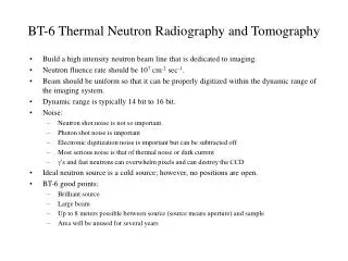
In a typical design of neutron radiography facility, the neutron moderation is done by way of polyethylene. The moderator is a cube of 60 cm on each side. The collimator is a cone with 1.5 mm thick cadmium lining the inner wall of the conical hole in the paraffin moderator (Fig. 4), The inlet and outlet apertures are 5 cm and 15 cm in diameter respectively. To reduce gamma contamination the inner wall of the cadmium cone has been lined with a 6 mm thick cone of lead. To further reduce the gamma ray component reaching the film plane, 2.5 cm of bismuth (two plugs each of 12.5 cm thick) was placed in the collimator adjacent to the inlet aperture. Also a flat 1.6 cm thick lead gamma shield was added around the collimator opening to shield the entire face of the moderator. To improve the quality of the thermal neutron beam reaching the film plane, a 15 cm thick lithium-loaded paraffin slab (50 wt per cent lithium hydroxide monohydrate) was also added to absorb stray neutrons emanating from the face of the moderator. The 252Cf source guide tube was inserted at the centre of the moderator via a cylindrical hole directly opposite and along the axis of collimator. Charlie Chong/ Fion Zhang
Figure 3. Two important factors in a collimator design, viz. geometric unsharpness (Ug) and output thermal neutron flux (Φo). For high resolution Ug should be small and for short exposure times the Φoshould be large. Both these requirements are contradictory. Charlie Chong/ Fion Zhang
Figure 4. Schematic diagram of a typical radiography facility using Californium-252 and an optical Collimator design. Bismuth Plug x 2 Collimator 252Cf Source Guide Tube polyethylene ? Core (material?) Cd Core Pb Core Li Wax Shield Charlie Chong/ Fion Zhang
To improve the quality of the thermal neutron beam reaching the film plane, a 15 cm thick lithium-loaded paraffin slab (50 wt per cent lithium hydroxide monohydrate) was also added to absorb stray neutrons emanating from the face of the moderator. The 252Cf source guide tube was inserted at the centre of the moderator via a cylindrical hole directly opposite and along the axis of collimator. A L/D ratio of 20 (fixed) has been used. Characteristics of the system are: Charlie Chong/ Fion Zhang
A new polyethylene moderator with a gadolonium oxide collimator has been developed and has replaced the paraffin moderator-cadmium collimator system. The thermal neutron flux at the film plane per milligram of 252Cf has increased by 1¼ times because of increased hydrogen density (from 0.891 g/cm3). Charlie Chong/ Fion Zhang
2.3 Imaging Neutrons themselves do not affect a photographic plate, and neutron radiographs cannot be made directly. Instead, images are formed through a suitable neutron-tocharged particle converter screen held adjacent to photographic film (the direct exposure method) or on a screen that becomes activated and is later placed adjacent to a photographic film activation- ransfer method). ■ ■ Direct exposure neutron radiography In direct exposure neutron radiography, the convertor screen and the film are both exposed together to the neutrons, just behind the specimen under test. The converter screen must have a high thermal neutron capture cross-section and emit radiations. like alpha4He+, or soft beta particles β or visible light (Photon) (and γ as nuisance?). It is these secondary radiations which form the image on the film much in the same way as the intensifying screens in X- radiography. The canverter screens are normally used as back screens, i.e. The screen is placed behind the film, to reduce the scattering of secondary radiations inside the screen to a minimum. Charlie Chong/ Fion Zhang
The most widely used screen for this technique is thin gadolinium (~ 12μm thick). Gadolinium has a high neutron absorption cross-section and emits 70 keV electrons. These low energy elecrons are easily stopped in the film emulsion with minimum spread, thereby giving high resolution capacity (<10μm). Typical neutron intensity required for an optical density of 1.5 on crystallex film is about 3 x 10⁸n/cm2. Scintillators made with 6Li or 10B, ZnS and a binding material are the fastest converter screens (about 100 times faster than Gd). However, resolution capability is poorer (~ 50μm) due to finite size of ZnS grains. The limit of exposure time is set by the gamma radiation level present in the beam. Most of the photographic neutron detectors using converter screens require an exposure of 105n/cm2∙sec to equal the film response to 1 mR of 60Co gamma radiation. A neutron to gamma intensity ratio of at least 105n/cm2/mR is therefore necessary to minimise the gamma interference in the radiograph. (?) Charlie Chong/ Fion Zhang
The thermal neutron radiographs taken with 252Cf source are of a quality at least equal to those with 241Am-Be and242Cm-Be sources. Some of the scintillator-film combinations used are given below: (i) 6Li-ZnS scintillator screens with radiographic films and with polaroid photographic films. Exposure time 10 min with type 52 film to 10 sec with type 57 film; Kodak Blue brand film and NE 425 scintillator; Kodak AA film and NE 425 scintillator; Kodak Blue Brand film and glass scintillator similar to NE 900 scintillator; Kodak AA film and glass scintillator similar to NE 900 scintillator; Boron loaded ZnS scintillator. (ii) (iii) (iv) (v) (vi) Charlie Chong/ Fion Zhang
■ ■ Activation transfer neutron radiography If the specimen itself is radioactive (e.g. nuclear fuels, reactor components) or the thermal neutron source has an unfavourable neutron to gamma ratio (much less than 105n/cm2/mR), direct exposure method has limitations, High gamma background causes excessive film fogging, resulting in a poor quality radiograph (lack of contrast and detail). In such circumstances activation transfer neutron radiographic technique is used. In this method, a converter screen is exposed alone to the neutron beam and becomes radioactive on neutron absorption. A latent image of the specimen is formed on the screen which is then transferred from the beam area to a photographic film in a remote place and allowed to decay. The secondary radiations now expose the film resulting in a radiograph which is free from gamma interference. The main requirements for such a transfer screen are high neutron absorption cross-section and moderate as well as convenient half life after activation. The three most commonly used materials are In, Dy and Au. Charlie Chong/ Fion Zhang
Transfer Technique The three most commonly used materials are In, Dy and Au. Charlie Chong/ Fion Zhang
Transfer Technique The three most commonly used materials are In, Dy and Au. Charlie Chong/ Fion Zhang
This radiography method was demonstrated to be possible with a 3.83 x 10⁸ n/sec 252Cf source if less of collimation and long exposure times are used. A film density of 0.62 was obtained using 0.13 mm Dysprosium foil, Kodak Royal blue films, ,1.5 m x 1.5 m x 9 m collimator, saturation exposure, and transfer times of a few hours. Lead screens 0.25 mm thick were adjacent to the film during transfer. Charlie Chong/ Fion Zhang
Some of the activation combinations used are given below: (i) Three gadolonium secreens of different sizes and small lead screen mounted in the casettee to be in contact with Du Pont NDT-75 film (exposure 1 to 2 hr). (ii) Kodak type R single-emulsion film (Slower-fine grain type) and gadolinium back-screens (exposure 16 hr). (iii) Transfer exposure methods with indium and dysprosium foils, Kodak Blue Brand and AA films and a neutron flux of 3 x 10³ n/cm2∙sec. (iv) Gadolinium with either Industrial GX-ray film or Kodak Royal Blue film is less sensitive and requires 8 hr exposure. Kodak Trix film requires exposure of about 1 hr. Charlie Chong/ Fion Zhang
■ ■ Filmless Radiography Both direct exposure method and activation transfer technique require costly films or dark-room equipment. Two techniques are cited below which do not require films and are of recent development. (a) Track Etch Radiography In this technique 6Li, 10B or 235U loaded screens are used to convert thermal neutrons to charged particles or fission fragments. When these secondary particles which have high specific ionization fall on certain plastics, they cause radiation damage along their paths. When selectively etched with suitable chemicals the damage becomes visible and a radiograph results. The advantages of this method are that it is (1) completely gamma insensitive, (2) has no limit on exposure, has good resolution characteristics and is simple to adopt. The main disadvantage is that it has a poor contrast (?) . Kodak Pathe‘ (France) is marketing cellulose nitrate films coated on both sides with a thin layer of lithium-borate. Typical exposures for a good radiography require 109n/cm2. Charlie Chong/ Fion Zhang
Transfer Method Scintillators Method Track-Etched Direct Gadolinium Method spatial resolution value of 50μm spatial resolution value of 10μm spatial resolution value of 50-100μm spatial resolution value of 25μm The contrast sensitivity for 25 mm steel or uranium objects is 1%. The contrast sensitivity for 25 mm steel or uranium objects is 2%. The contrast sensitivity for 25 mm steel or uranium objects is 4~6%. The contrast sensitivity for 25 mm steel or uranium objects is 1%. Typical screen In, Dy Typical screen Gd, Li Typical screen LiF-ZnS and gadolinium oxysulfide Typical screen Li or B 104n∙cm-2minimum 105n∙cm-2 (film) 3 x 10⁶ n∙cm-2s-1 (30 frames/s) 109n∙cm-2 109n∙cm-2 ?μm thick 25μm thick Charlie Chong/ Fion Zhang
(b) Electronic Image Recording Thermal Neutron Radiography In addition to the metal film combinations, or solid state track etch detector screen systems, electronic image recorders have also been tested for neutron radiography. These recorders were developed for an immediate inspection of objects during any manipulation or movement. A small 200 μg 252Cf source with an inexpensive shielding consisting of plates of borated wood and gypsum as well as lead, a divergent collimator of L/D ratio 20:1 and a thermal flux level of 4.7 x 10²n/cm2-sec has been used in combination with the following commercial components for electronic image recording thermal neutron radiography. Charlie Chong/ Fion Zhang
(i) A neutron scintillator screen containing a mixture of 6Li-ZnS (Ag) in aninorganic matrix (Type NE 426). A three stage electrostatic image intensifier H XX 9955 with an overall gain in brightness of 3 x 10⁴which views the scintillator by using a sensitive optic bus system (objective 1:10). A Secondary Electronic Conduction (SEC) television camera tube SEC H-1004 which is fiber optically coupled to the rear output face plate of the image intensifier. The SEC tube gives possibility to accumulate single events-which may be indiscernible in normal scanning periods of 1/25 seconds-into an image. By scanning of SEC target after an appropriate integration time (several seconds) the image can be released and observed in a monitor coupled with the video output of the camera. (ii) (iii) Charlie Chong/ Fion Zhang