Download
1 / 36
360 likes | 515 Vues
Renewal Energy Application to ILC. T. Saeki (KEK) 15 May 2014 AWLC2014 at FNAL. Improve Efficiency of Power Consumption in Accelerator Operation. Green ILC. serious issue for ILC. Power Balance of Consumption and Loss in ILC. ILC 500 GeV Total Power : ~ 200 MW.

E N D
Renewal Energy Application to ILC T. Saeki (KEK) 15 May 2014 AWLC2014 at FNAL
Improve Efficiency of Power Consumption in Accelerator Operation Green ILC serious issue for ILC
Power Balance of Consumption and Loss in ILC ILC 500 GeV Total Power : ~200 MW Improve efficiency loss rate 50 % : 25 MW 50 % : 35 MW 90 % : 60 MW 100 % : 10 MW ~ 130 MW Infrastructure : 50 MW RF System : 70 MW Cryogenics : 70 MW Beam Dump : 10 MW 200 MW Obligation to Us Increase recovery
Activities for Green ILC • Three presentations were given (by A. Suzuki, D. Perret-Gallix, and M. Yoshioka) in 2nd WS “Energy for Sustainable Science at Research Infrastructure” at CERN in Oct. 2013. • A session (four presentations) was organized for Green-ILC activities in LCWS 2013 at Tokyo in Nov. 2013. A. Suzuki also presented Green-ILC activities in the plenary session in LCWS 2013. • Green-ILC Working Group was organized in “Advanced Accelerator Association promoting science & technology (AAA) in Tokyo/Japan. The 1st meeting for the Green-ILC WG of AAA was held on 25th February 2014. (AAA home page = https://aaa-sentan.org/en/about_us.html ) • 2nd Green-ILC WG meeting was held on 5th May 2014 in Tokyo/Japan. Some realistic technologies of energy-saving for ILC were proposed and discussed by industries and scientists. • D. Perret-Gallix is preparing the interactive home page of Green-ILC and is going to launch it soon.
Advanced Accelerator Association promoting science & technology (AAA) Association by industries and scientists • 96corporate organizations involved from industries (MHI, Toshiba, Hitachi, Mitsubishi Electronics, etc.) as of May 2014. • 40 institutional organizations involved from universities and laboratories (KEK、Univ. of Tokyo、Univ. of Tohoku, Univ. of Kyoto, Riken, etc.) as of May 2014. Organization of AAA Green-ILC WG started in Technology Study Group on 25th Feb. 2014. 6
Agenda for the 2nd AAA Green-ILC WG meeting Date: 8th May 2014 (Thu.) 13:30 - 17:00.Place: 6th floor, UDX Building in Akihabara, Tokyo.1) Collector Potential Depression (CPI) Klystron (30 min.) by Toshiba Electron Tubes & Devices Co. Ltd. 2) Power Saving of Large-Scaled Helium Compressor (30 min.) by Mayekawa Manufacturing Company.3) Examples of New Energy Power Plants (20 min.) by RIKEN.4) Solar Power Plant (40 min.) by Japan Photovoltaic Energy Association5) Proposal of Biomass Power Plant for ILC (20 min.) by Kabuki Construction Co. Ltd.
Agenda for the 2nd AAA Green-ILC WG meeting Date: 8th May 2014 (Thu.) 13:30 - 17:00.Place: 6th floor, UDX Building in Akihabara, Tokyo.1) Collector Potential Depression (CPI) Klystron (30 min.) by Toshiba Electron Tubes & Devices Co. Ltd. 2) Power Saving of Large-Scaled Helium Compressor (30 min.) by Mayekawa Manufacturing Company.3) Examples of New Energy Power Plants (20 min.) by RIKEN.4) Solar Power Plant (40 min.) by Japan Photovoltaic Energy Association5) Proposal of Biomass Power Plant for ILC (20 min.) by Kabuki Construction Co. Ltd.
How to Improve RF Efficiency R&D of CPD (Collector Potential Depression) Klystron CPD is an energy-saving scheme that recovers the kinetic energy of the spent electrons after generating rf power. Conventional Schematic diagram of CPD collector collector
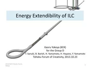
Multi(6) – Beam Klystron (MBK) for 26 Cavities for ILC • The design goal is to achieve 10 MW peak power with 65 % efficiency at 1.5 ms pulse length at 10 Hz repetition rates. • MBK has 6 low-perveance beams operated at low voltage of 115 kV for 10 MW to enable a higher efficiency than a single-beam klystron.
Present Status of R&D Target proof-of-principle of CPD in the unsaturated region (a maximum rf power of 500 kW) using a KEKB 1.2MW-klystron • Newly fabricated components • collector • ceramic insulator • output cavity • output coupler R&D Schedule 2013.3: Modification of an existing klystron to CPD klystron (already done) 2014.3: until then, preparation and commissioning of the test station ~2014: Verification of klystron operation without CPD ~2015: Measurement of rf leakage from the gap between the body column and the collector (with no CPD voltage applied) Measurement of induced pulse voltage on the collector with CPD ~2017: Test of rectification by Marx circuit Integration test of the proof-of-principle of CPD operation • Recycled components • electron gun • input cavity • intemediate cavities Goal : 80 % efficiency
Agenda for the 2nd AAA Green-ILC WG meeting Date: 8th May 2014 (Thu.) 13:30 - 17:00.Place: 6th floor, UDX Building in Akihabara, Tokyo.1) Collector Potential Depression (CPI) Klystron (30 min.) by Toshiba Electron Tubes & Devices Co. Ltd. 2) Power Saving of Large-Scaled Helium Compressor (30 min.) by Mayekawa Manufacturing Company.3) Examples of New Energy Power Plants (20 min.) by RIKEN.4) Solar Power Plant (40 min.) by Japan Photovoltaic Energy Association5) Proposal of Biomass Power Plant for ILC (20 min.) by Kabuki Construction Co. Ltd.
Heat source from the helium compressor Low stage Compressor 50% 100% Power input Inter cooler 50% High stage compressor After cooler Oil separator 3% Oil cooler 3% Chilled water Heat source Oil cooler 47% 2.5% 5% 47% 42% Temperature balance of the oil cooler Adsorption chiller AdRef 313K ≒363K Before Cooling water 313K ≒358K ≒363K After
Heat Source AdRef New refrigeration cycle with AdRef Low suction temp. →small compressor →small power consumption 4.25MW(100%) 3.97MW(93%) 300K 270K Waste Heat(5%) Waste Heat(5%) ILC ⊿3MW (45.81→ 42.79MW) 310K 310K Waste Heat(95%) 280K Waste Heat(93%) 4kW(0.1%) Compact cold box & HEX 270K 280K 80K 80K 18kW 18kW Conventional cycle New cycle with AdRef
Agenda for the 2nd AAA Green-ILC WG meeting Date: 8th May 2014 (Thu.) 13:30 - 17:00.Place: 6th floor, UDX Building in Akihabara, Tokyo.1) Collector Potential Depression (CPI) Klystron (30 min.) by Toshiba Electron Tubes & Devices Co. Ltd. 2) Power Saving of Large-Scaled Helium Compressor (30 min.) by Mayekawa Manufacturing Company.3) Examples of New Energy Power Plants (20 min.) by RIKEN.4) Solar Power Plant (40 min.) by Japan Photovoltaic Energy Association5) Proposal of Biomass Power Plant for ILC (20 min.) by Kabuki Construction Co. Ltd.
CGS (Go-Generation System) at RIKEN • 6.5 MW + 2720 USRT • 1Hz (20msec) power switch for blackout. • Efficiency:68%,as of June 2010. • G:7MVA. 6.6kV. 50Hz. • T :1100℃/480℃. 14000rpm. 6.6MW /12℃. • B :480℃/160℃. 1.6MPa(210℃)12.5t/h • C :400 USRT x 5 + 360 USRT x 2, 7℃ at outlet (1 USRT=3.52kW. )
Power Line Circuit GT Spare Cooling Water Acc. Building Big-RIPS SRF Magnet SRC Magnet He Refrig. Vac. Acc. Control CGS Load
Agenda for the 2nd AAA Green-ILC WG meeting Date: 8th May 2014 (Thu.) 13:30 - 17:00.Place: 6th floor, UDX Building in Akihabara, Tokyo.1) Collector Potential Depression (CPI) Klystron (30 min.) by Toshiba Electron Tubes & Devices Co. Ltd. 2) Power Saving of Large-Scaled Helium Compressor (30 min.) by Mayekawa Manufacturing Company.3) Examples of New Energy Power Plants (20 min.) by RIKEN.4) Solar Power Plant (40 min.) by Japan Photovoltaic Energy Association5) Proposal of Biomass Power Plant for ILC (20 min.) by Kabuki Construction Co. Ltd.
Solar Power Production / Top 6 Countries Integrated Installation (2012) Installation per Year (2012) German German Japan Japan MW/Y MW German German Japan Japan
Projection of Solar Power Production in Japan by IEA Projection done in 2013 (WEO2013) Projection done in 2012 (WEO2012) Integrated Solar Power Production in Japan (GW) Year +2000
Smart Country by Smart GRIG Solar power: >50 GW at 2030 in Japan
Agenda for the 2nd AAA Green-ILC WG meeting Date: 8th May 2014 (Thu.) 13:30 - 17:00.Place: 6th floor, UDX Building in Akihabara, Tokyo.1) Collector Potential Depression (CPI) Klystron (30 min.) by Toshiba Electron Tubes & Devices Co. Ltd. 2) Power Saving of Large-Scaled Helium Compressor (30 min.) by Mayekawa Manufacturing Company.3) Examples of New Energy Power Plants (20 min.) by RIKEN.4) Solar Power Plant (40 min.) by Japan Photovoltaic Energy Association5) Proposal of Biomass Power Plant for ILC (20 min.) by Kabuki Construction Co. Ltd.
❑ 有機性廃棄物利用バイオマス発電 Biomass Power Plant using Organic Waste Conceptual Biomass Town around ILC Lake Farming (Animals) Farming (Fruits) Farming Park Methane Ferment Factory Recycling Factory Compost Factory Lumber / wood industries Organic Waste Process Machine Traffic Stores Offices Factories Biomass waste Unutilized Biomass Biomass Diesel Fuel Factory Residences Power / Products 出典:土浦市バイオマスタウン構想書
❑ Estimate of Biomass Electric Power ILC (TunnelHeat Waste) Estimate of Electric Power Assuming the efficiency of 10~20% Kitakami Site58,104 kW×10 ~20% = 6,000~10,000kW Sefuri Site 43,280 kW×10 ~20% = 5,000~10,000kW Regional usage: Farming Hospital Tourism・・・ Heat Recovered Heat Various Biomass Drying Electric Generation Direct Burning Steam Watercontent 15 % Water content 15 – 90 % Recycling Products Burned Ash
Summary • The 1st meeting for the Green-ILC WG of AAA was held on 25th February 2014 to launch the Green-ILC activity. • The 2nd Green-ILC WG meeting was held on 5th May 2014 in Tokyo/Japan. Some realistic technologies of energy-saving for ILC were proposed and discussed by industries and scientists. 1) Collector Potential Depression (CPI) Klystron (30 min.) by Toshiba Electron Tubes & Devices Co. Ltd. 2) Power Saving of Large-Scaled Helium Compressor (30 min.) by Mayekawa Manufacturing Company. 3) Examples of New Energy Power Plants (20 min.) by RIKEN. 4)Solar Power Plant (40 min.) by Japan Photovoltaic Energy Association 5) Proposal of Biomass Power Plant for ILC (20 min.) by Kabuki Construction Co. Ltd. • Proposed items for energy-saving for ILC might be summarized and written in the report under the framework of AAA.
Simplified Schematic Concept Without CPD With CPD Potential in the Klystron Potential in the Klystron Electron Energy Electron Energy Uk Uk RF RF Potential & Electron Energy E0 E0 Potential & Electron Energy Ec Uc E1 E1 CPD gap Ec Uc Efficiency of RF Conversion (40-50) % Beam Deceleration Anode Heat Loss Energy Recovery/Reuse Anode Cathode Cathode Collector Collector Output cavity Output cavity Potential denotes the electron potential energy, eV. For simplicity, input and intermediate cavities are omitted here and the anode potential is set to zero.
Issues must be addressed for CPD Klystron (I) Energy spread The spent electron beam has large energy spread through electromagnetic interaction in the cavities. Therefore, the collector potential cannot be increased beyond the lower limit of energy distribution of the spent electron beam, otherwise backward electrons hit the cavities or the gun, and then deteriorate the klystron performance. Output Coupler Collector Unsaturated: 200 kW out Saturated: 1 MW out E0 = 90keV E0 = 90keV Ceramic Insulator (II) Pulse-to-DC conversion The spent electron beam is longitudinally bunched, so that pulsed voltage is induced on the collector. An adequate pulse-to-DC converter has to be implemented. (III) RF Leakage CPD klystron has to be equipped with an insulator between the collector and the body column in order to apply CPD voltage to the collector. Thus, it would be possible for the CPD klystron to leak rf power out more or less from the insulator.
Adsorption chiller “AdRef” Environmentally Friendly Chiller. Features 1. No CFCs, HCFCs used. Water (H2O) is used as refrigerant. 2. Low temperature heat source. As low as 65 C 3. Super Energy Saving Only a few HP necessary 4. Easy maintenance Very few moving parts used. 5. Safe No pressure piping or refrigerant
Adsorption chiller “AdRef” Vapor H2Ois removed from adsorber “B” by heating with warm water, and condensed in the condenser by the cool of cooling water. Adsorber Adsorber Liquid water goes to the evaporator. Cooling water Heat source AB The adsorber “A” adsorb vapor H2O by cool of cooling water. Then the liquid H2O in the evaporator evaporates, and the latent heat cool down the chilled water. Vapor H2O Evaporator Condenser Cooling water Water pump Chilled water
Adsorption chiller “AdRef” Vapor H2Ois removed from adsorber “B” by heating with warm water, and condensed in the condenser by the cool of cooling water. Liquid water goes to the evaporator. Adsorber Adsorber Heat source Cooling water AB The adsorber “A” adsorb vapor H2O by cool of cooling water. Then the liquid H2O in the evaporator evaporates, and the latent heat cool down the chilled water. Vapor H2O Evaporator Condenser Heating/Cooling of adsorber A/B is switchedperiodically. Cooling water Water pump Chilled water
Absorption refrigerator (chiller)(from Wikipedia, the free encyclopedia) • An absorption refrigerator is a refrigerator that uses a heat source (e.g., solar, kerosene-fueled flame, waste heat from factories or district heating systems) to provide the energy needed to drive the cooling system. • In the early years of the twentieth century, the vapor absorption cycle using water-ammonia systems was popular and widely used, but after the development of the vapor compression cycle it lost much of its importance because of its low coefficient of performance (about one fifth of that of the vapor compression cycle). Nowadays, the vapor absorption cycle is used only where waste heat is available or where heat is derived from solar collectors. Absorption refrigerators are a popular alternative to regular compressor refrigerators where electricity is unreliable, costly, or unavailable, where noise from the compressor is problematic, or where surplus heat is available (e.g., from turbine exhausts or industrial processes, or from solar plants).