Download
1 / 13
130 likes | 153 Vues
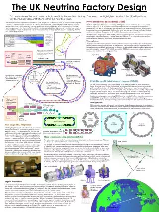
Neutrino Factory Nozzle Layouts. V.B. Graves NFMCC Friday Meeting Apr 10, 2009. Goals. To compare the Neutrino Factory Study II target layout with results from current studies Identify some mechanical issues that will need to be resolved. General Target Concept.

E N D
Neutrino Factory Nozzle Layouts V.B. Graves NFMCC Friday Meeting Apr 10, 2009
Goals • To compare the Neutrino Factory Study II target layout with results from current studies • Identify some mechanical issues that will need to be resolved
General Target Concept Neutrino Factory Study 2 Target Concept SC-5 SC-2 SC-3 SC-4 Window SC-1 Nozzle Tube Mercury Drains Mercury Pool Proton Beam Water-cooled Tungsten Shield Mercury Jet Iron Plug Splash Mitigator Resistive Magnets ORNL/VG Mar2009
NF Study II Dimensional Info (unchanged) Based on Study II Tables 3.13, 3.14 Dimensions in cm
NF Study II Z Reference • From Section 3.1.2 • Locates jet relative to solenoids
Current Jet/Beam Parameters • Recent studies have caused changes to baseline target parameters • Consideration of gravity on jet trajectory moves nozzle below beam • Maximizing particle production requires steeper beam angle • New conditions • Beam • Angle: -80 mrad, crosses magnet axis at Z=0 • Size: 0.4 cm dia • Jet • Nozzle angle: -48 mrad • Nozzle location: Z=-50cm, Y=+2.7cm • Jet angle at Z=0: -60 mrad • Jet size: 0.4 cm dia • Jet center intersects beam center at Z=0
NF/IDS Jet Trajectory • Jet curved trajectory included in model • Beam will intersect pieces of dispersed jet all the way to the pool Jet (0.4cm dia) Beam (0.4cm dia)
NF/IDS Pool • Current jet parameters show pool entrance at ~ 2m • Pool has 1 deg slope for drainage • Splash mitigation not shown • Pool definition certainly not finalized!
Nozzle Piping • Beam angle limits how short the tapered section of nozzle piping can be • Current lore suggests shorter taper may be preferred for jet quality, but not possible with these dimensions • Image shows 2” pipe & flange upstream of 50-cm-long taper
Nozzle Close-up • Current clearance 4mm • Required clearance around beam TBD
Clearance for Pion Collection • Study 2 baseline defined in MUC0289 and MUC0296 (2004). • Magnetic field “tapers” from B = 20 T at z = 0 to B = 1.8 T at z = 12.2 m. • Pions within r = 7.5 cm at z = 0 stay within the curve shown below, which reaches r = 25 cm at z = 12.2 m.