Download
1 / 15
150 likes | 291 Vues
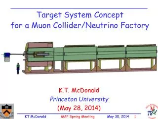
Neutrino Factory Target Cryostat Review. Van Graves Cale Caldwell IDS-NF Phone Meeting August 10, 2010. General Target Concept – Downstream Mercury Drain. Neutrino Factory Study 2 Target Concept. SC-5. SC-2. SC-3. SC-4. Window. SC-1. Nozzle Tube. Mercury Drains. Mercury Pool.

E N D
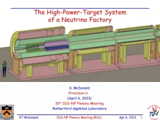
Neutrino Factory Target Cryostat Review Van Graves Cale Caldwell IDS-NF Phone Meeting August 10, 2010
General Target Concept – Downstream Mercury Drain Neutrino Factory Study 2 Target Concept SC-5 SC-2 SC-3 SC-4 Window SC-1 Nozzle Tube Mercury Drains Mercury Pool Proton Beam Water-cooled Tungsten Shield Mercury Jet Iron Plug Splash Mitigator Resistive Magnets ORNL/VG Mar2009
NF Cryostat with Tapered Shielding • Taper matches capture field • No shielding under mercury • Straight W-C bore up to beam window to allow removal of mercury chamber
Cryostat Modules • All insertion/extraction from upstream end • Locating & supporting features not shown – will require additional space
Cryostat Modules Full View • Module weight supported by cryostat? Probably not – another structure required • Remote handling of these modules not trivial • Note slot in shielding module for mercury chamber
Assembled Cryostat • Resistive magnet leads & water cooling for these modules also enter from upstream
V2: 10cm Shielding Below Resistive Magnets, 15cm Above • Allows mercury drainage below magnets while still providing W-C shielding
V2 Iso: 10cm Shielding Below Resistive Magnets, 15cm Above • Asymmetric W-C structure, minimal shielding for SC1
V3 Iso: 30cm Shielding Below, 35cm Above, Constant ID • Simpler W-C shielding fabrication, sized to protect SC1
Some Questions as Design Progresses • Can system perform without iron plug and/or resistive magnets? • Removal simplifies remote maintenance, provides more space for nozzle & beam dump. • What does internal cryostat structure (weight support, magnet force restraints) look like, and how does it affect overall cryostat size? • Are 5 SC magnets required in this cryostat? • Downstream beam window should be at end of cryostat for remote maintenance from downstream end. • What shielding thickness is required to protect SC1? • This will ultimately drive cryostat bore diameter.
Summary & Reminders • Current NF target design based on physics performance characteristics • Further considerationshows it is an assembly of several subsystems, each with different design requirements and trade-offs • Several areas of engineering-related R&D, including heat removal, Hg flow, nozzle development, beam windows • With Hg target, hands-on maintenance cannot be assumed at any point in operation • Remote features must be incorporated into initial design • Final system concept will result from an integrated design approach with input from several technical areas