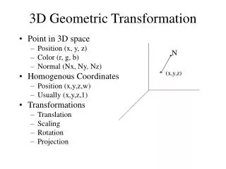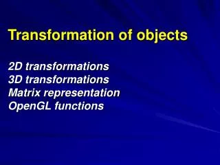
3D Transformation P ipeline
3D Transformation P ipeline. 3D Transformation Pipeline. Modeling Coordinates. Modeling Transformation. World Coordinates. Viewing Transformation. Viewing Coordinates. Projection Transformation. Projection Coordinates. Workstation Transformation. Device Coordinates.

3D Transformation P ipeline
E N D
Presentation Transcript
3D Transformation Pipeline Modeling Coordinates Modeling Transformation World Coordinates Viewing Transformation Viewing Coordinates Projection Transformation Projection Coordinates Workstation Transformation Device Coordinates
Viewing Coordinates To choose a particular view for a scene: • Establish a viewing coordinate system • Setup a view plane or projection plane perpendicular to the Zᵥ axis • Transform the world coordinate positions in the scene to viewing coordinates • Project viewing coordinates on to the view plane.
Right handed viewing coordinate system is used • View reference point is the origin of the ‘VCS’ Viewing Coordinate System • World Coordinate Positions are to be transformed to viewing coordinates
Viewing System or ‘uvn’ System • Select the positive direction for the viewing Zᵥ axis • Select the orientation of the viewplane by specifying view plane normal N (relative to either WCS as is commonly done, or to ‘vcs’) • Next specify up direction for the view using the view-up vector V. This vector sets positive direction of the Yᵥ axis. • Direction of V must not be parallel to N when selected.
Viewing System or ‘uvn’ System • Viewing procedures typically adjust the user defined orientation of vector V so that V is projected on the plane perpendicular to N. • Using V and N graphics package can compute U perpendicular to both N & V. • The viewing system is often described as ‘uvn’ system.
Step: 2 Step: 1
Step: 3 Step: 4
Observations: • Generally graphics packages allow users to select viewing plane along Zᵥ axis by specifying viewing plane distance from viewing origin • View plane is always parallel to Xᵥ Yᵥ plane • Projection of objects onto view plane constitutes the scene • Right handed viewing systems are common as WCS is also right handed, therefore orientation remains same
Observations: • To get series of views of a scene, keep view reference point same and change direction of N • Thus we can view scene from any direction except along the line of V • To simulate camera motion through a scene, keep N fixed and move the view reference point around.
VIEWING TRANSFORMATION • Mapping from world to Viewing coordinates • Origin moves to eye position • Up vector maps to Y axis • Right vector maps to X axis
Transformation from WC to VC General sequence of translate-rotate transformation • Transformation sequences • 1. Translate the view reference point to the origin of the WC system • 2. Apply rotations to align the xv, yv, and zv axes with
Transformation from WC to VC • Translation • view reference point(x0, y0, z0) • Rotation • rotate around the world xw axis to bring zv into the xwzw plane • rotate around the world yw axis to align the zw and zv axis • final rotation is about the zw axis to align the yw and yv axis
Transformation from WC to VC • Rotation by uvn system • Calculate unit uvn vectors • N : view-plane normal vector • V : view-up vector • U : perpendicular to both N and V • Form the composite rotation matrix
Viewing Parameters • Position • Eye position(px, py, pz) • Orientation • View direction(dx, dy, dz) • Up direction(ux, uy, uz) • Aperture • Field of view(xfov, yfov) • Film plane • “look at” point • View plane normal
Canonical coordinate system • Canonical coordinate system • Convention is right-handed (looking down – z axis) • Convention for projection, clipping, etc.
Mapping • Transformation matrix maps camera basis vectors to canonical vectors in viewing coordinate system