Development of a Detector Testing Facility at Kansas State University
This project overview covers the design considerations, system testing, and conclusions of a detector testing facility at Kansas State University. The facility includes Generation I and II diffraction systems, with emphasis on neutron detectors. The K-State Reactor history, SMART Labs installation, and specific labs for crystal growth and testing are detailed. Design considerations like floor loading constraints and shielding manipulation are discussed, along with beam intensity implications and collimator design. Generation I and II systems are described, focusing on motion controls, monochromators, and shielding requirements.

Development of a Detector Testing Facility at Kansas State University
E N D
Presentation Transcript
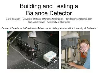
Development of a Detector Testing Facility P. M. Whaley Kansas State University
Overview • Introduction & Motivation • Design Considerations • Generation I Diffraction System • Generation II Diffraction System • System Testing • Conclusions
K-STATE REACTOR • 1960: Construction Permit 100 kW Facility Operating License • 1962: Initial criticality • 1968: 250 kW (with pulsing) license
Reactor Experiment Facilities • 2 Thermal columns • Reflector well • In-core tubes • Beam ports NEBP (piercing) NWBP (radial) • NEBP difficult • SEBP heavily used • SWBP lightly used • NWBP dormant SWBP (radial) SEBP (tangential)
Beam Port Access door seal Inner Plug Outer Plug
K-State Reactor • 2000: Recovery of operating time • 2002: Renewal request (to 1.25 MW) • 2002: SMART Labs installed at K-State
K-State SMART Laboratories • Design & production of radiation detectors • Semiconductor-based radiation detectors • Gas-filled radiation detectors • Major research emphasis on neutron detectors • Opportunities for reactor utilization • Committed NWBP to diffracted beam test facility • Low gamma contamination • Monoenergetic neutrons • Set of facilities for specific processes/functions
Crystal Growth & Testing Labs CdZnTe Growth Condensation/Deposition Lab HgI2 (B) Material Testing HgI2 (A) Surface & Volume Characterization
Processing Labs Crystal Growth Class 1000 Clean Room Processing Vacuum/vapor deposition Ion Mills & Plasma Etching Surface Examination
DESIGN CONSIDERATIONS • Floor loading constraints • Shielding manipulation • Motion controls • Beam intensity • Collimator
Floor Loading Constraints • Beam centerline 30 in. from floor • Bay floor rated to110 lb ft-2 (UBC) • Concrete density nominally 150 psf • Untenable limit for shielding mass • KSU Architect certified design 350 lbf ft-2 • Based on soil compaction • Very limiting, but workable • Elevated shielding minimizes weight
Shielding Manipulation • Manageable with facility equipment • Overhead crane • Manual pallet jack • Powered pallet jack • Elevated • Positioned to shield beam • Reduced floor loading • Stability possible issue
Motion Controls • Limited resources • Computer interface, 2-axis controls • Rotation • Elevation • Adjustable crystal orientation • Experiments show floor extremely stable to impulse loading
Beam Intensity Implications • MB distribution • Peak energy about 50 meV • Harmonics not an issue • approximately 1% flux available • NWBP thermal flux 6x10⁷ n cm-2 s-1 • Estimate 105 n cm-2 s-1 near peak energy available at monochromator
Collimator Design • Beam & monochromator size • Shielding requirements compete with intensity • Radial beam port gamma is severe • Limit consequences of beam port leakage • Options to: • Evacuate flight tube (10% m-1 loss in air) • Install high energy neutron & gamma filters • Install instrumented equipment core-side
GENERATION I SYSTEM • Motion controls/Monochromator • Collimator • Shielding
Generation I Motion Controls • Newport 2-axis controller • Rotation stage • Goiniometer stage • Stages mounted on vibration damper • Labview controls • Scan rotation • Change angle of elevation
Generation I Monochromator • Silicon monchromator cut from thcik, “perfect” crystal
Generation I Shielding • Rotating shield/integral shutter • Apertures for 2 angles & main beam • Elevated platform to minimize mass • Wire enclosure
Generation I Collimator • 1 ½ inch tubes (3) for flight tube variations • Penetrations for inst., gas or cooling lines • Active seal on beam port flange • Thin Al plates seal flight tube in a flange • Connectors for vacuum or helium (1 tube)
Generation I Conclusion • Min. footprint & weight, adequate shielding • Low intensity • Clear peak
Problems • Resources with appropriate knowledge • Personnel • Limited experience • Diffracted beam intensity • Perfect crystal: high resolution, low intensity • Mosaic permits range of energies • Inducing mosaic spread in Si is not trivial • Shielding aesthetics
GENERATION II SYSTEM • Research Assistant • Large collimator • Motion controls & monohromators • Cannibalized Huber theta-2theta stack • LabView Virtual Instrument motion control • Shielding
Graduate Available Soon • Licensed reactor operator • LabView programming • MCNP modeling • 3-D CADD (fabrication & CNC drawings) • Mechanical aptitude & abilities • Maintenance & repairs laboratory equipment • Millwright & pipefitting • ABC News feature “Can I get your picture? My roommate will never believe that a couple of cute girls visited the reactor.”
Gen II Monochromator Stand Monochromator Stage Stage to locate beam
Gen II Monochromators • Pyrolitic graphite • Silicon • Crystal bender
Gen II Collimator Mounted Thin Al window Vacuum connection
Filter Tests Bismuth Sapphire
System Testing • Measurements of spectrum • Monochromator tests for intensity • Filter test for operational characteristics
Monochromator Tests • Silicon • Bent Silicon • Pyrolitic graphite
Conclusions • Facility is essentially complete • Remount area monitor • Finish enclosure • Experiment status sensor • Testing programs in progress
Lessons Learned • Bias of experience affected perceptions • Spectral measurement as a lab exercise • Using a system versus • Building a system • Copper monochromator • Beam extracted from D2O tank adj. to core • Filtering (bismuth & sapphire) perceptions • Not needed • Degrades intensity unacceptably
Lessons Learned • Crystal orientation perception: • Need to have the crystal fully indexed • Flats in Si wafer indicate principle plane • Mosaic spread was not considered necessary
Lessons Learned • Design objectives need to: • Reflect actual needs • Be specified and fixed • Concrete terminology • Concrete is rated for structural load • Architectural load is different • Focus on beam, disregarding background