Building and Testing a Balance Detector
140 likes | 278 Vues
This project focuses on the design and testing of balance detectors that measure laser beam intensity differences. The detectors yield output voltage proportional to the intensity difference between two laser beams. A prototype was built and tested, demonstrating high sensitivity, detecting imbalances of 1 μW in the 15-200 μW range. This work is part of a novel experiment to test general relativity on a tabletop setup in Professor John Howell’s lab at the University of Rochester. Acknowledgments to my advisor and research program contributors are included.

Building and Testing a Balance Detector
E N D
Presentation Transcript
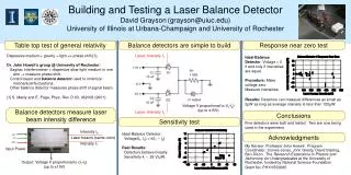
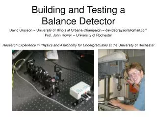
Building and Testing a Balance Detector David Grayson – University of Illinois at Urbana-Champaign – davidegrayson@gmail.com Prof. John Howell – University of Rochester Research Experience in Physics and Astronomy for Undergraduates at the University of Rochester
Balance detectors measure laser beam intensity difference Input Power Intensity I2 -15 V Laser beams (same color) 0 V +15 V Intensity I1 Output: Voltage propotional to (I1-I2) (up to ±15V) Voltage is 0 when I1=I2
Balance detectors are useful • Prof. Howell’s lab: A novel new experiment to test general relativity on the tabletop • David Starling • Manuel Alves • Prof. Howell’s dream Manny
Our balance detectors are simple Original detector built by Michael Pack Circuit diagram obtained by examination.
I built two balance detectors BD1 BD2
The balance detectors were sensitive enough Sensitivity = Slope = .27 V/μW Sensitivity = Slope = .24 V/μW
Response near zero output voltage sensitivity intensity intensity V = k(I1 – I2) Procedure: Too hard • Adjust the system to make I1 = I2 • Measure V • Adjust the system to make V = 0 • Measure I1-I2
The balance detectors’ response near zero was good Result: Imbalances of 1 μW are detected in the 15-200 μW range. Result: Imbalances of 1 μW are detected in the 15-200 μW range.
Acknowledgments • My Advisor: Professor John Howell • Program Coordinator: Connie Jones • The Research Experience in Physics and Astronomy for Undergraduates at the University of Rochester, funded by National Science Foundation Grant No. PHY-0552695. • John Gresty • David Starling • Ben Dixon Questions? Contact David Grayson, davidegrayson@gmail.com
I made a quick prototype • Used only equipment that I found in the lab
The prototype was sensitive enough Sensitivity = Slope = .26 V/μW