Download
1 / 34
340 likes | 605 Vues
ME 6405 Student Lecture Transistor. Cong Zhao Feifei Qian Kuan -Wen Tung October 2, 2012 Georgia Institute of Technology. Contents. 1. Introduction to Transistor (Speaker: Cong Zhao). 2. Bipolar Junction Transistor (Speaker: Feifei Qian ). 3. Field Effect Transistor

E N D
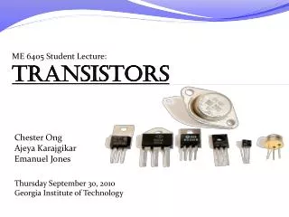
ME 6405 Student LectureTransistor Cong Zhao FeifeiQianKuan-Wen Tung October 2, 2012 Georgia Institute of Technology
Contents 1 Introduction to Transistor (Speaker: Cong Zhao) 2 Bipolar Junction Transistor (Speaker: FeifeiQian) 3 Field Effect Transistor (Speaker: Kuan-Wen Tung) 4 Power Transistor (Speaker: Kuan-Wen Tung)
Introduction • Question #1: How can we control the TV with remote-controller? • Question #2: How can a computer recognize 0(off) and 1(on) for computing? Amplifier and Electronic Switch are needed. • Amplifier: any device that changes, usually increases, the amplitude of a signal. • Electronic Switch: switch that the physical opening and closing is achieved by applying appropriate electrical control signals. Amplifier and Electronic Switch are needed.
Introduction • However, Vacuum Tube is too big, fragile, and energy-consuming. • Early 20th century, vacuum tube was used for the amplifier and switch. ENIAC, the first general-purpose electronic computer, contains 17,468 vacuum tubes. Vacuum Tube Radio Transistor solved this problem.
Introduction – Invention of Transistor • Invention • In 1947, John Bardeen, Walter Brattain, and William Schockly, researchers at Bell Lab, invented Transistor. • They found Transistor Effect: “when electrical contacts were applied to a crystal of germanium, the output power was larger than the input.” • In 1956, they were awarded the Nobel Prize in physics. John Bardeen, Walter Brattain, and William Schockly First model of Transistor, 1947
Introduction – Definition of Transistor A transistor is a three-terminal semiconductor device that amplifies or switches the flow of current between two terminals by varying the current or voltage between one of the terminals and a third.
Introduction – Semiconductor • Semiconductor • is a material that has an electrical resistivity between that of a conductor and an insulator. • has a few charge carriers(“holes” or free electrons). • the conductivity increases by adding impurities or dopants(doping). Silicon is used in most commercial semiconductors
Introduction – Doping • Doping:add neighboring elements to the semiconductor to make it electropositive or electronegative • P(positive)-type doping is adding Acceptor impurities (from Group III) to the semiconductor in order to increase holes. • Ex: Silicon doped with Boron • N(negative)-type doping is adding Donor impurities (from Group V)with more electrons in order to increase free electrons. • Ex: Silicon doped with Phosphorous Add Group III(Boron) Add Group V (Phosphorous)
Introduction – P-N Junction • PN Junction • is a junction formed by P-type and N-type semiconductors together in very close contact. What happens at the junction? • Thin depletion region forms near junction at an equilibrium condition (Zero bias) • Near the p–n interface, electrons from N diffuses into P, leaving positively charged ions in N region; holes from P diffuses into N, leaving negatively charged ions in P region • Ions exhibit a force which inhibits further carriers flow across the P-N Junction unless a forwardbias external voltage is applied.
Introduction – Forward and Reverse Bias • Forward bias • -V pumps electrons into the N-region. • +V pumps more holes into the P-region. • Excess of charge in P and N region will apply pressure on the depletion region and will make it shrink. • → current flows • Reverse bias • -V sucked out electrons from N-region. • +V sucked out holes from P-region. • The depletion layer widens and it occupies the entire diode(p-n). • → current doesn’t flow
Introduction – Transistor • Transistor is comprised by two P-N junctions: Base-Collector junction and Base-Emitter junction.
Introduction – Types of Transistor • Transistor are categorized by • Semiconductor material: germanium, silicon, gallium arsenide, etc. • Structure: BJT, FET, IGFET (MOSFET), IGBT • Polarity: NPN, PNP (BJTs); N-channel, P-channel (FETs) • Maximum power rating: low, medium, high • Maximum operating frequency: low, medium, high • Application: switch, audio, high voltage, etc. • Physical packaging: through hole, surface mount, ball grid array, etc. • Amplification factor • General Purpose Transistors • Bipolar Junction Transistor (BJT) • Field Effect Transistors (FET) • Power Transistors n-channel JFET NPN BJT
Introduction • A bipolar junction transistor (BJT) is a three terminal semiconductor device in which the operation depends on the interaction of both majority and minority carriers and hence the name Bipolar. • It is used in amplifier and oscillator circuits, and as a switch in digital circuit. • It has wide applications in computers, satellites and other modern communication system.
Three Regions in BJT • Emitter is heavily doped so that it can inject a large number of charge carriers into the base. • Base is lightly doped and very thin, therefore it passes most of the injected charge carriers from the emitter into the collector. • Collector is moderately doped and larger in size, so that it collects the major portion of the majority carriers supplied by the emitter.
Transistor biasing • NPN: • BE forward biased • BC reverse biased • PNP: • BE reverse biased • BC forward biased
BJT Transistor Operation http://www.learnabout-electronics.org/bipolar_junction_transistors_05.php
Regions of Operation BJT Switch “On” Linear mode BJT Switch “Off”
Transistor as a Switch • When a transistor is used as a switch, it is usually required to be brought alternatively in the saturation and cut-off conditions. • When in saturation condition, it should carry heavy current, so the voltage drop across the transistor is as near to zero as possible. It may be considered as “closed switch”. • When in cut-off condition, it should carry almost no current so that it may be considered to be an “open switch”.
Transistor as an Amplifier Transistor Configurations
Transistor as an Amplifier • Use small digital signal to turn coils on/off
By Kuan-Wen Tung Field Effect Transistor, FET
What makes a FET? 3 terminal device with: • Drain • Source • Gate The body has contacts at the ends: the drain and source Gate surrounds the body and can induce a channel by use of electric field
What is a FET? FET Semiconductor device that uses electric field to control current, thus, the channel conductivity. Unipolar transistor involving single carrier type operation, in contrast to BJT. Relies on PNP or NPN junctions to allow current flow Performs same functions as a BJT; amplifierand switch.
How does FET work? E=id*R+vd Basic operation: Assume a 2-terminal device with nonlinear I-V characteristics Add a third terminal to control the I-V curve by changing voltage • Result: change in the current flowing through the first 2 terminals Application: Amplification : increase current id by increasing gate voltage. Switching : change gate voltage to switch device on, vice versa.
Types of Field-Effect Transistors NPN nMOS PNP pMOS NPN nMOS PNP pMOS NPN nMOS PNP pMOS
Metal-Oxide-Semiconductor, MOSFET nMOS Four terminal device: • Source, gate, drain, and body (substrate) that connects to source Enhancement mode of operation • Positive gate voltage required to conducting channel for nMOS device to turn on. • Negative gate voltage for pMOS device to turn on.
How does a MOSFET work? nMOSdevice in enhancement mode Equilibrium energy band diagram Operation: VGS > Vth Structure: • Device formed on lightly doped p-type substrate. • Source and drain are heavily doped with n-type. • Oxide layer separates gate from Si surface. • Result: N-P-N type, nMOS.
Enhancement Mode of Operation FETs vary voltage to control current. Triode Mode/Linear Region VGS > Vth and VDS < ( VGS - Vth ) Saturation/Active Mode VGS > Vth and VDS > ( VGS - Vth ) VGS : Voltage at the gate Vth : Threshold voltage VDS : Voltage from drain to source
Characteristics and Applications of MOSFET • Oxide layer prevents DC current from flowing through gate • Reduces power consumption • High input impedance • Rapid switching • Noisy due to undesired capacitive behavior • Applications: • Used as switches and amplifiers in general • Used in digital CMOS logic, which uses p- and n-channel MOSFETs as building blocks • CMOS: Complementary MOS Circuit Layout Symbol: Not Function/ Inverter
Power Transistors • Built to carry and dissipate more power as opposed to tiny transistor • has low current gain • Used in high voltage and high current application • Used in high switching frequency of 100 kHz (switch in <1 μs) • Provides current limit protection • Cannot withstand reverse voltage • Different types: Power BJTs, power MOSFETS, etc. • Application: RF and microwave power transistors, multiple chip device • Limitation: limited to dc voltage for inverters
References • [1] “Solid State Electronic Devices" Ben G. Streetman. • [2] Student Lecture Fall 2010. • [3] Student Lecture Fall 2011. • [4] “Electronic Circuits – Handbook for Design and Applications” U. Tietze and Ch. Schenk. • [5] “Transistors." http://en.wikipedia.org/wiki/Transistor • [6] “FET.” http://en.wikipedia.org/wiki/Field-effect_transistor • [7] “JFET.” http://en.wikipedia.org/wiki/JFET • [8] “MOSFET.” http://en.wikipedia.org/wiki/MOSFET • [9] “MOSFET Animation.” http://www.youtube.com/watch?v=v7J_snw0Eng • [10] “Class Lecture #6 on Digital Arithmetic 2012.” Dr. Charles Ume • [11] “Class Lecture #4 on CMOS Inverter 2010.” Dr. MiltiadisHatalis